posts
-
The SuperCollider Book - 2nd edition
The second edition of the SuperCollider Book is published on April 29th, 2025, by MIT Press.
This edition features updates to two chapters I had also contributed to the first edition: Ins and Outs: SuperCollider and External Devices and Spatialization with SuperCollider.
And of course many more updates and new chapters by all the other contributors to the book!
Thanks to the editors Scott Wilson, David Cottle and Nick Collins.
The SuperCollider book
published by MIT Press
Description from MIT:
A comprehensive update of the essential reference to SuperCollider, with new material on machine learning, musical notation and score making, SC Tweets, alternative editors, parasite languages, non-standard synthesis, and the cross-platform GUI library.
SuperCollider is one of the most important domain-specific audio programming languages, with wide-ranging applications across installations, real-time interaction, electroacoustic pieces, generative music, and audiovisuals. Now in a comprehensively updated new edition, The SuperCollider Book remains the essential reference for beginners and advanced users alike, offering students and professionals a user-friendly guide to the language’s design, syntax, and use. Coverage encompasses the basics as well as explorations of advanced and cutting-edge topics including microsound, sonification, spatialization, non-standard synthesis, and machine learning.
Second edition highlights:
- New chapters on musical notation and score making, machine learning, SC Tweets, alternative editors, parasite languages, non-standard synthesis, SuperCollider on small computers, and the cross-platform GUI library
- New tutorial on installing, setting up, and running the SuperCollider IDE
- Technical documentation of implementation and information on writing your own unit generators
- Diverse artist statements from international musicians
- Accompanying code examples and extension libraries
-
Mention in the Volkskrant in Rewire review
Dutch national newpaper the Volkskrant reviewed the Rewire festival and has much praise for N-Polytope, while being quite critical of the organisation of the Rewire festival:
Translation by me (original Dutch below):
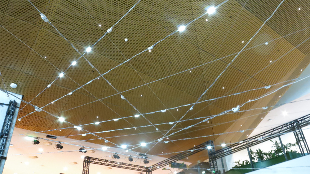
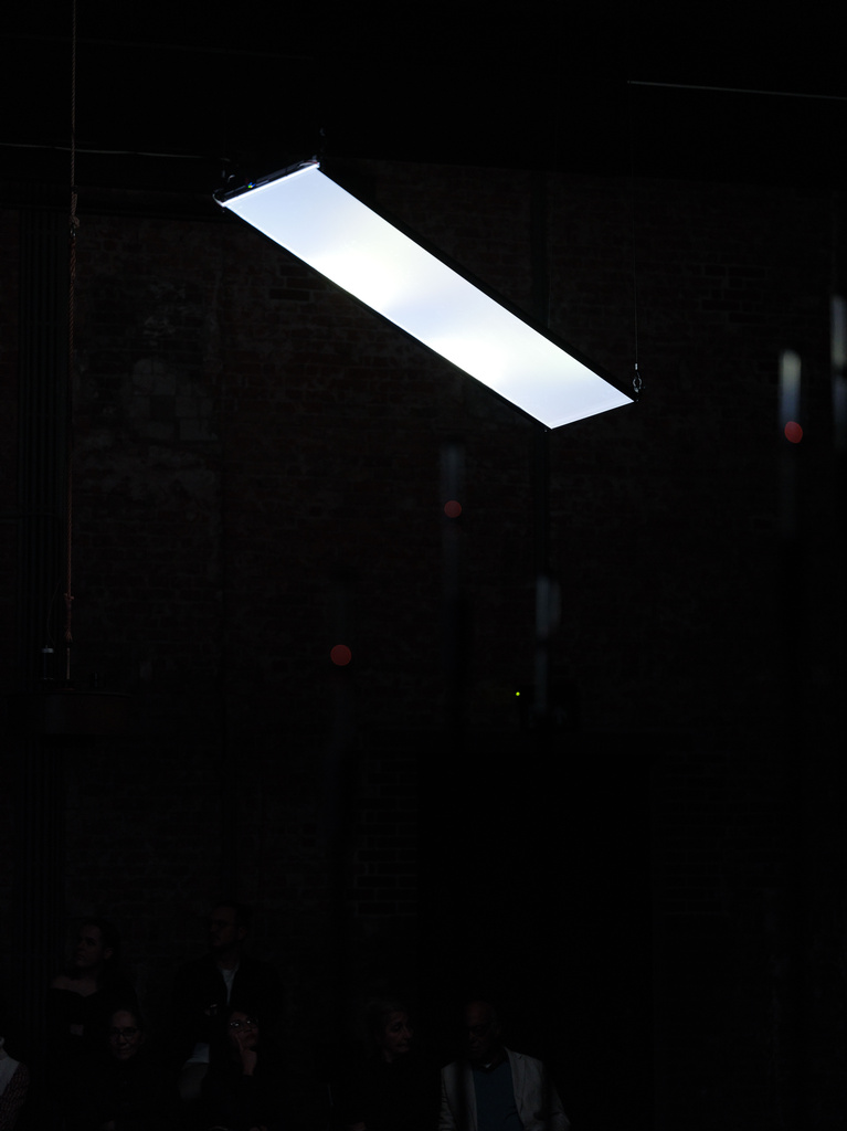
The lucky ones to obtain a ticket [to the festival], get their wristbands in the foyer of the concert hall Amare. Behind the cash counters the first disappointment is found. And no, not artistically. The show N-Polytope by Marije Baalman and Chris Salter is a multimedia spectacle that buzzes around you from four speakers.
The artwork seems to be electrified: music tantalizes the ears, on highly tensioned wires led lamps are flickering. With N-Polytope Baalman and Salter want to reflect on early electronic work of the Greek composer Iannis Xenakis. That is not a misplaced bluff: their piece is a sparkling answer to the cosmic works that Xenakis composed in the 1970s with his self-invented computer program UPIC.
But why N-Polytope is presented on the staircase, right in front of the entrance, is a mystery. If one work needs a quiet, dark room, this one does. In broad daylight people are walking around, and chats and hugs are exchanged. It is like playing mikado in stormy weather: no matter how powerful N-Polytope is, little remains.
Choosing the location was weighing the pros and cons: yes, for attention of audience to experience the light and sound in its full depth, a fully dark space would have been preferable. But then the piece would have been set up in a blackbox space, have only been accessible for three days during the festival and have only attracted people who would choose to go to this blackbox. The architecture of the work would have had little interaction with the architecture of the venue it was presented in. Instead we chose for a location where a lot of people would encounter the work, also people who would not normally go and visit a work like this. Also the interaction between the architecture around the staircase in Amare and the architecture of the work have a nice interaction now. And as a plus: the work stays exhibited for a total of two months, making the time, effort and money invested in realising the show more than worthwhile.
Original Dutch text:
De geluksvogels die een ticket hebben bemachtigd, halen hun bandjes op in de foyer van concertgebouw Amare. Achter de kassa’s vindt de eerste teleurstelling plaats. En nee, niet op artistiek gebied. De voorstelling N-Polytope van Marije Baalman en Chris Salter is een multimediaspektakel dat uit vier speakers om je heen gonst.
Het kunstwerk lijkt onder stroom te staan: muziek tintelt de oren, aan hooggespannen kabels knipperen ledlampen. Baalman en Salter willen met N-Polytope reflecteren op vroeg elektronisch werk van de Griekse componist Iannis Xenakis. Dat is geen misplaatste bluf: hun stuk is een sprankelend antwoord op de kosmische werken die Xenakis in de jaren zeventig met zijn zelfbedachte computerprogramma UPIC componeerde.
Maar waarom N-Polytope op de trap, recht voor de ingang, wordt gespeeld, is een raadsel. Als er één werk is dat een stille, donkere ruimte nodig heeft, is dit het wel. In het volle daglicht wandelen mensen rond, er worden praatjes en knuffels uitgewisseld. Het is als mikado spelen bij windkracht 12: hoe krachtig N-Polytope ook is, er blijft weinig van overeind.
- “Rewire Festival maakt op artistiek gebied iedere verwachting waar, maar: de organisatie laat te wensen over”, Dennis Bajram, Volkskrant, April 7, 2025
-
Video of Intricate Interplays
Video of Intricate Interplays by Tanja Busking, created by iii.
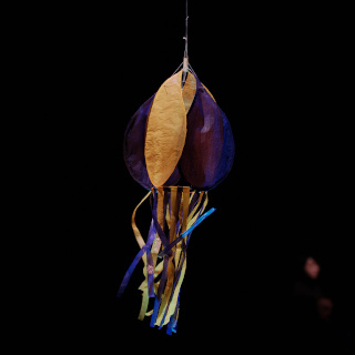
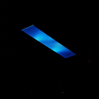
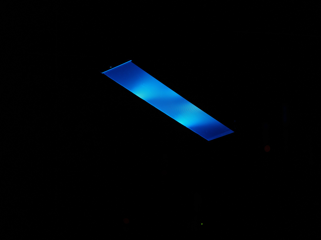
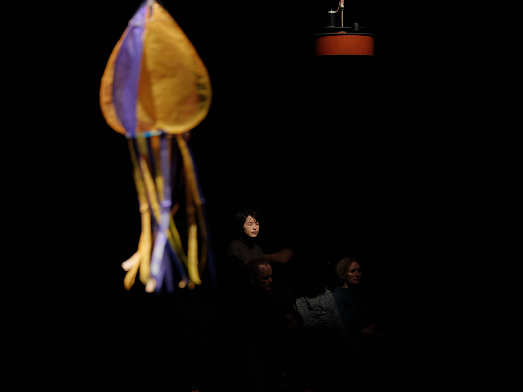
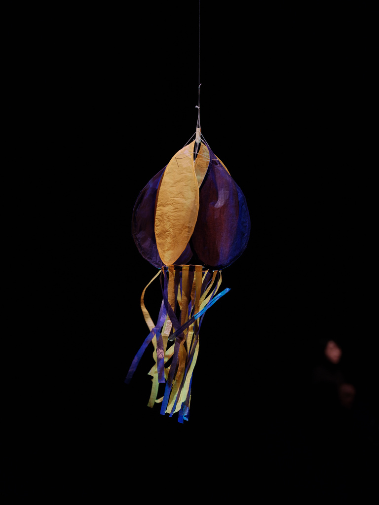
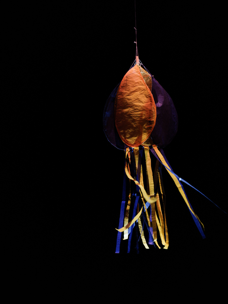
November 30th, I took part in a joint performance with various artists from iii (Mariska de Groot, Dieter Vandoren, and Mihalis Shammas) and Ludmila Rodrigues at Korzo theater in Den Haag.
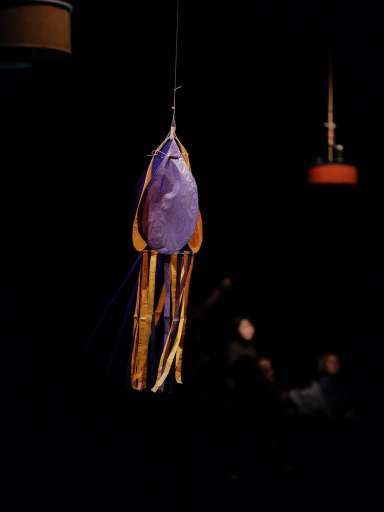
In the performance I particated with two new instruments: light plates and an instrument made of paper and rotan controlled by wind. This last instrument is a first attempt to play with wind indoors.
-
Documentation of Intricate Interplays
November 30th, I took part in a joint performance with various artists from iii (Mariska de Groot, Dieter Vandoren, and Mihalis Shammas) and Ludmila Rodrigues at Korzo theater in Den Haag.
In the performance I particated with two new instruments: light plates and an instrument made of paper and rotan controlled by wind. This last instrument is a first attempt to play with wind indoors.
photos by Davide Sartori, Intricate Interplays, iii @ Korzo
Light plates
Wind
-
Looking back at 2023 and outlook into 2024
In 2023, I have been doing various presentations at different occasions - a highlight being the keynote presentation at the International Livecoding Conference in Utrecht.
In the background I have worked on Baken (beacon), which will be a permanent light installation mounted on the new building of the artist incubator space Bajesdorp. This is still a work in progress as I am gathering the financial support to realise this project. However, I have worked on prototypes and first explorations with this new kind of light instrument.
The biggest achievement of 2023 is the completion of the new Bajesdorp: a housing cooperative and artist incubator, that over 2023 has grown from its foundations into a finished and delivered building of 20 meters high. So at the end of 2023 and beginning of 2024, I have been busy with finalising the inside of my new home and atelier.
We have founded a new association in June 2023, Begane Grond Bajesdorp, that will run the public spaces on the ground floor. A crowdfunding campaign has just started in February to kickstart GROND.
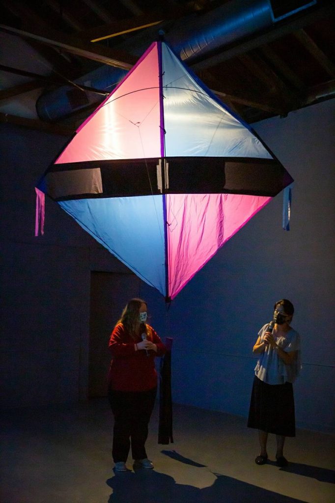
In 2024, I will be working one or two new works with kites - so stay tuned for that!
-
Looking back at 2022 and outlook into 2023
Last year, I published my book “Composing Interactions” after many years of researching, writing, creating diagrams and perfecting the layout. I’m very happy with all the positive reactions that I am getting on the book now that it is out into the world.
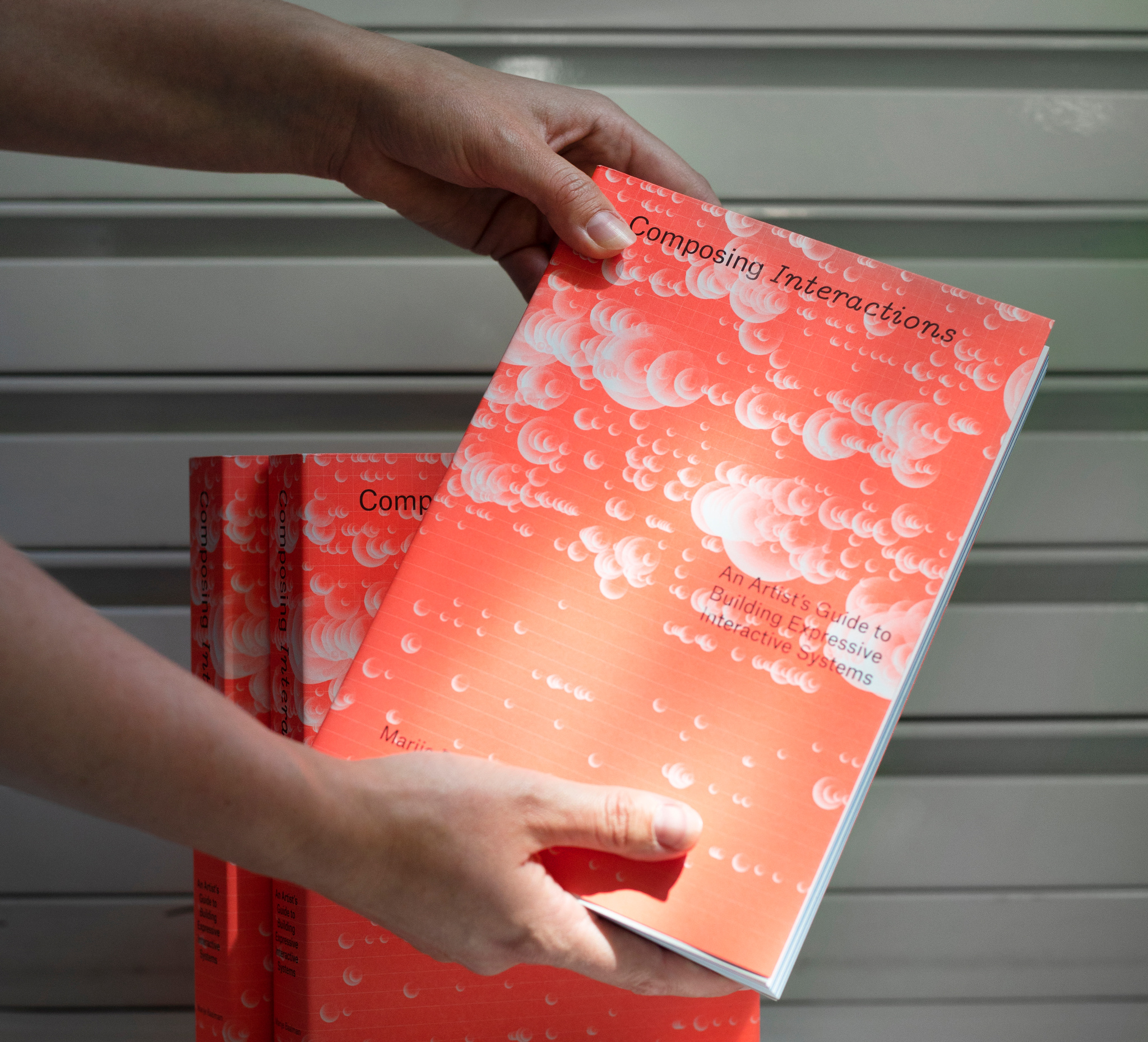 photo by Felicity van Oort
Also in 2022 I had the opportunity to return to my kite projects and developed a new version of V.L.I.G. adapting the work to a video installation with footage recorded at the beach of Tainan. That work is still in exhibition at Siao-Long Cultural Park. In addition, I developed a workshop on creating musical instruments from kites, and presented the performance Wind Instrument again.
In 2023, I will focus on the work Baken (beacon), which will be a permanent light installation mounted on the new building of the artist incubator space Bajesdorp. The light installation will be driven by locally measured environmental data and will over time make visible the change in the local climate. This work brings many new challenges with it, ranging from making a weatherproof, durable installation, composing for multicolor lights, and working with a combination of realtime and prerecorded data from a database, to find relations between the now, yesterday, and the further past. I am currently working on creating a team to work with, funding applications to be able to realise and building prototypes to try things out.
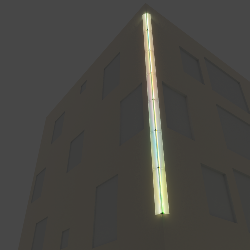 virtual model of the light art work in Blender (Luuk Meints)
At the same time, I am involved in the new project of Frouke Wiarda, The Turbine Plays. This project deals with the energy transition, mainly focusing on wind mills. Some further concepts for new works in a series of “Beacons of Transition” are in my head, and from the research with the work I will see how these ideas will develop.
Some time this year, a new edition of “The SuperCollider Book” will also come out with MIT Press, featuring updated versions of two chapters: “Ins and Outs: SuperCollider and External Devices” and “Spatialization with SuperCollider” that I (co-)authored for the book.
I also have taken up the opportunity, to clean up my website a little bit - at the top, you now only see a few highlighted projects, and if you click on the header or the menu item at the top, you will get to the full list. This will hopefully make it a bit easier to see what I am currently working on, while still preserving the overview of all the projects I have done over the past 10 years or so.
-
Presales of Composing Interactions
After many years of writing, the publication date of my book Composing Interactions - An Artist’s Guide to Composing Interactions is now finally in sight, and set at June 1st, 2022. The presales have started via the publisher V2_.
-
Behaviours of light and sound
This post was originally written in 2018, but then not published on the website yet. I’m happy to post it now, finally!
In this post, I will describe how the sound and light composition of N-Polytope is structured. For this I will start with the physical components, describe the sound synthesis and light synthesis algorithms, and then go to the bigger picture of the composition with these instruments and how the machine learning algorithms are used.
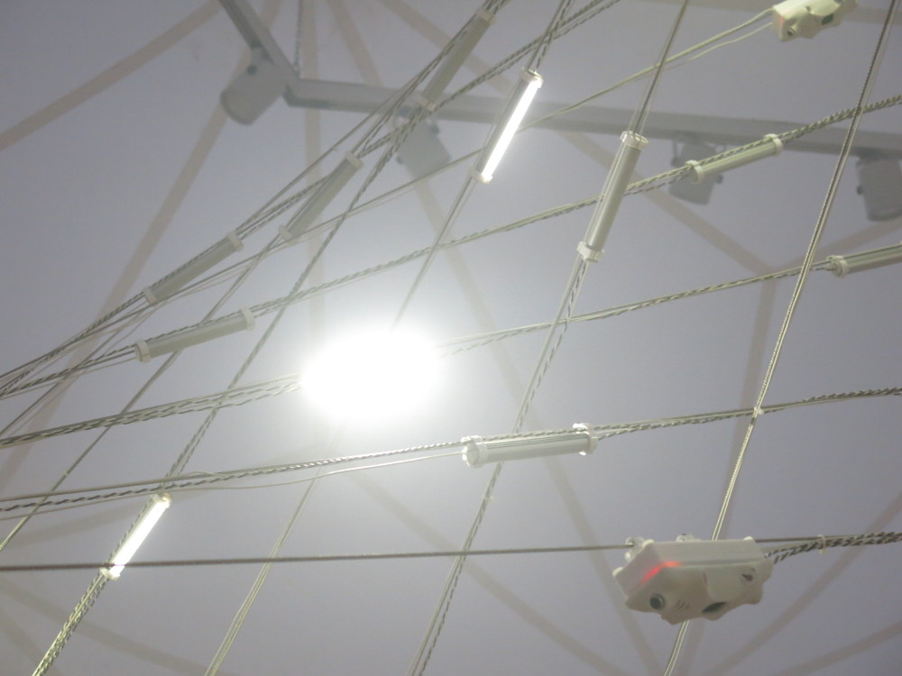
N-Polytope is a re-imagination of Xenakis’s Polytope works. For this work we were inspired to use similar steel cable structures that look like curved planes, folded into each other. For each location where N-Polytope is presented, the steel cable structure is adapted to the space were the work is exhibited and we try to create a connection with the architecture of the space.
On the steel cable structures modules are mounted that generate light and sound and also measure light and sound. The measurements are sent to a central computer which runs various machine learning algorithms over the course of the 14-minute composition. The timeline of the composition is determined by an additional ‘fixed media’ soundtrack composed by Chris Salter and Adam Basanta. This soundtrack is played over 4 broad range speakers situated around the space and 2 subwoofers.
The physical components
The modules on the steel cable structures consist of
- a microcontroller (Atmega328p)
- a second microcontroller (ATTiny841) that is programmed for sound synthesis
- an XBee for wireless communication
- 3 light dependent resistors (LDR)
- 1 electret microphone
- connections to three LEDs which are mounted separately on the steel cable
The Atmega328p is the core of the module and handles wireless communication (via the XBee) with the main computer, measurements of the LDR’s, amplitude tracking of the microphone, communication with the ATTiny841 to control the sound synthesis, and pulse width modulation patterns for the LEDs.
Modular computation
Sound synthesis
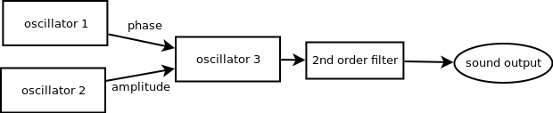
The ATTiny841 is programmed with a fixed sound synthesis patch of three wavetable oscillators, where one oscillator controls the amplitude of the third one, and another the phase of the third one. Then after the third oscillator there is a 2nd order filter. Then the result is sent to a DAC, connected to a small amplifier and the speaker of the module.
Each oscillator has parameters for
- the frequency
- the waveform (sine, sawtooth, triangle, pulse, dc, noise)
- the envelope, with attack and decay
- the duration
- the amplitude
- to play once or repeat the envelope
For the waveform, only the third oscillator can be noise generator (not a wavetable then), and only the first two oscillators can be DC (so not a waveform, but a fixed value).
The synthesizer can be triggered with a wireless message from the computer.
For the frequency and duration parameters you can set a base value and a range within which a random value is chosen upon triggering the synthesis which is added to the base value. Then there are three modes for using the random range: no randomness (so just use the base value for the parameter), setting the randomvalue once when the setting is sent to the synthesizer, and choosing a random value each time the synthesizer is triggered.
Light synthesis
For controlling the lights also a synthesis approach is chosen: the computer just sends parameters for the light pattern and then sends triggers to start the sequence.
For each LED there is an oscillator with
- a range for the intensity between which the LED oscillates
- duty cycle (how long the waveform is)
- frequency
- waveform (triangle, sawtooth, reversed sawtooth, pulse, noise and DC)
- duration
- once or repeat (waveform cycle)
Also here the frequency and duration can be set with a base value and a range for a random value to be added, with the same random modes as for the sound synthesis.
Sensing
The microcontroller is also reading out the microphone data at audio rate and doing a very simple envelope following on the measured value.
And the microcontroller is reading out the three LDR’s at a lower rate (1/6th of the audio rate): the microcontroller switches between reading the microphone signal and one LDR: so a sequence of microphone - LDR 1 - microphone - LDR 2 - microphone - LDR 3, and so on. This sequence ensure that the microphone is read out at a constant sample interval. For the LDR’s the speed is not so important as the light levels change on a much slower time scale.
Communication
Finally, the microcontroller handles the communication with the main computer: it sends out the sensor data at a regular interval, and continuously listens for incoming messages that set the paramaters for the light and sound synthesis or trigger the LEDs or sound.
Also the sound synthesis microcontroller reports its calculated amplitude, which is send along with the sensor data. Reading out this communication also checks that the ATTiny841 is still up and running. If there is no communication for a while, the Atmega328p will reset the ATTiny841.
Concepts
In making these modules, there were a number of considerations.
On the microcontroller I had to negotiate tradeoffs between the processing power of the microcontroller and its memory size, the bandwidth for the wireless communication, and having a flexible system for experimentation and composition. Changing and updating the firmware is a tedious process that involves opening all the housings, taking out the microcontroller board, uploading the firmware, and putting the board back. Not a quick task with around 50 units, mounted on steel cables and for which a ladder or something else may be needed to reach the unit.
We wanted to have a system with many modules - creating actual sound sources that are spread out over the space, rather than using virtual sound sources in multi-speaker sound spatialisation setups. So we chose to do the sound synthesis locally and send over parameters: hence no need for complex cabling and sound cards with many channels. At the same time, of course having a fixed sound synthesis algorithm limits the amount of possible sounds, but we found with the designed algorithm we could reach a large number of different types of sounds: from very resonant ‘rinkling’ sounds to noisy snoring like sounds. And even though each individual module only has a 1W amplifier with a small speaker, all together the system can reach a good level of loudness.
The addition of the randomness to the frequency and duration of the sounds is a way of implementing variation in the sounds: it allows us to use the same preset of parameters for all modules, while still having a variation of sounds. The base value plus a random value within a certain range is also akin to Xenakis’ concept of tendency masks - ranges within which parameters of sound vary over the course of time.
Also using a synthesis approach for the light is remeniscent of Xenakis’ concept of viewing light as something that happens over time: the light synthesis parameters describe how the light behaves within a short time window from its triggering.
The modules implement the possible micro-behaviours for the light and sound. The presets for these are then sent from the central computer. This leaves the freedom to try out new presets when the system is set up in a space, without having to reprogram the modules and at the same time it limits the amount of communication needed to the module (since wireless bandwidth is limited and wired communication would require a more complex setup and a lot more cables).
The compositional structure
As mentioned above the compositional structure then consists of a fixed media soundtrack and a score linked to it, that starts and stops:
- various machine learning algorithms,
- presets and parameter changes for light and sound synthesis algorithms
- additional tasks that sequence the triggering for light and sound
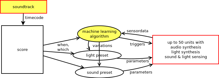
While composing the work, we (Sofian Audry, Chris Salter and myself) discussed the type of algorithms we would use: Sofian would program the algorithms using his machine learning library Qualia and I would choose what type of presets for the microbehaviour of the light and sound would fit to the algorithm and with the soundtrack. Then we would look at the behaviour of the algorithm and tune the parameters for the machine learning algorithm and the presets. The score also determines which modules are active at a given time: so we make interventions on where the machine learning algorithms are active and where not to create a spatial dramaturgy for the work.
The machine learning algorithms
The machine learning algorithms take different types of inputs: we have sensor data from the structure available: light and sound levels, and for some of the algorithms we use different metrics as well.
Some of the algorithms (booster and chaser) are based on reinforcement learning: the algorithm makes an observation (e.g. of the light and sound levels), determines an action to take, and then gets a reward which is calculated from a subsequent observation. The reward is simply a function of the values given in the observation: a mathematical formula. The algorithm then attempts to get the largest reward possible over time. Then it also has a parameter for how ‘curious’ or ‘exploratory’ it is to try out something new: take a complete different action in the hopes that the chosen action yields an even higher reward than it got with previous actions.
For all of the algorithms we are sending a trigger signal to calculate the next step for the calculation. This means that we can vary the speed of the algorithms.
Firefly
In the firefly algorithm each LED has three states: it can be flashing for a certain amount of time and after this time it will be ‘blind’ for a while: it will ignore its environment. If it is not flashing or blind, the LED will measure the amount of incoming light and compare that with the average amount of light over the past time (calculated from a moving average). When above the threshold, the a power variable will be increased and the firefly will be blind for a while.
Then the power variable is compared to a second threshold, and if it exceeds that threshold it will start flashing. If it has flashed for the set flash time, it will reset the blind time and the power variable and go back to the idle state.
Drunk
The drunk algorithm is a kind of random walk: the value for the LED intensity is a weighted sum of a random walk of a parameter for the overall grid, for each line, for each node and the individual LED.
For each parameter at each update a small random amount is added or substracted. Then the total value is calculated by adding the values up with a certain weight for how much influence each of the parameters has. If the weight for the overall grid would be 1 and 0 for the other parameters, all LEDs would do the same. So the weights determine the amount of variation between the individual LEDs: from all the same to all completely different.
This algorithm uses no other inputs than the weights for the four parameters. These weights are changed over the course of the section.
Booster
The booster algorithm has as many agents are there are modules. The agents have a neural network with 5 inputs, 8 hidden layers and 1 output. It then uses an epsilon-decreasing policy for learning, which means that at the start the agent is more exploratory and later on the agent is more greedy.
The inputs to the network are the measured light value, the moving average of the light value, a parameter energy and a timer. The energy is a slowly increasing value with time, and after a certain amount of time after emitting light, the energy increases also based on the light input. The reward is calculated from the emitted led values, with some linearity built in, that boosts the ‘right’ decisions and punishes ‘bad bursts’.
When the agent decides to emit light, the energy and the timer are reset to 0.
Chasers
In the chasers algorithm the spatial layout of the structure is taken into account. Each line is regarded as a one-dimensional space where a chaser can move around. While moving the chaser is rewarded for touching another chaser (be on the same position), moving, or staying in the same position. The position on the line is defined as the position of an LED, so if there are three modules with each three LEDs mounted on a steel cable, that line has 9 possible positions for a chaser to be. The position of the chaser is visualised by triggering the LED and auralised by triggering the sound of the module the LED belongs to. If the reward for the chaser is larger than 0.5 (the range is between 0 and 1), the parameter repeat is set for the light preset.
In the score, more and more chasers are added to each line. Initially the light preset is a short flash. Later on in the chaser section, the light preset is changed to a longer flickering light, creating more overall brightness in the space.
Note that in this algorithm the only input of the algorithm is the position of the other chasers - no sensor data is used.
Genetic algorithm
The genetic algorithm was added in 2017 for the exhibition at the MAC in Montreal. The idea was that instead of setting the parameters for the presets of the light and sound synthesis directly, a genetic algorithm would try to mutate from its current state to the new target state of the parameters. In this way the algorithm attempts to replicate the ‘normal’ score, but takes a bit of time before it has found the right parameter set.
The parameter set is interpreted as a string of bits (1’s and 0’s), a binary chromosome. At each step of calculation of the algorithm, it selects two members of the population, ‘mates’ them to create two new ‘children’ and selects the fittest of the two offspring, i.e. the one closest to the new target preset.
We created two instances of this algorithm: one with a population of the size of the number of nodes to approximate the sound presets, and one with a population the size of the number of LEDs to approximate the light presets.
The ‘genetic’ mode we thus created was then added as an alternative ‘ambient’ mode to play along the ambient soundtrack.
-
Interview on WoNoMute
I was interviewed by WoNoMute (Women Nordic Music Technology), a horizontal network organization that promotes the work of those identifying as women in the interdisciplinary field of music technology. The term music technology is used here to define activities related to the use, development and analysis of technology applied to sound and music. It is an umbrella term that connects researchers and practitioners, as well as engineers and social scientists. WoNoMute previously interviewed (amongst others): Rebecca Fiebrink, Rebekah Wilson, Pamela Z, Natasha Barrett and Alexandra Murray-Leslie.
Read the interview here: https://wonomute.no/interviews/marije-baalman/
-
Documentation of Wezen-Handeling
In this post, I am documenting the work Wezen-Handeling, as it was performed and livestreamed on May 7, 2021.
Documentation of Wezen - Handeling
This work is a sequel to Wezen - Gewording. The sound instruments that I use are similar to ones I developed for that piece. The code base and the processing algorithms have been redeveloped for this new piece.
In the work I am using inspiration from the work of different artists, whose work I studied as part of writing the book Just a question of mapping:
- pose detection: inspired by Cathy van Eck and Roosna & Flak
- flick detection: inspired by Roosna & Flak
- recording / playback of control data: inspired by STEIM’s The Lick Machine
- button processing: inspired by Erfan Abdi’s approach for chording
- the use of some control data to set starting parameters and others for continuous control is inspired by Jeff Carey.
- matrix / weights to connect input parameters to output parameters is inspired by Alberto de Campo’s Influx.
Sound layers
In Wezen - Handeling there are two different layers of sound:
- sound instruments triggered directly from movements with the left hand and controlled with the right hand
- sound instruments controlled from recorded triggers and movement data. This recorded data can be looped, sped up and slowed down, the playback length and the starting point in the recorded buffer can be changed, and additional parameters can be modulated.
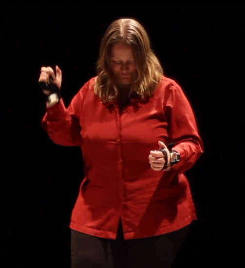
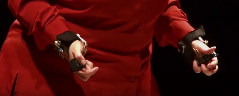
The controllers
The controllers that I use are open gloves with five buttons each (one for each finger) and a nine-degrees-of-freedom sensor. The data from these gloves is transmitted via a wireless connection to the computer, where it is translated to Open Sound Control data and received by SuperCollider. The core hardware for the gloves is the Sense/Stage MiniBee.
The gloves were orginally designed and created for a different performance, Wezen - Gewording, where the openness of the glove was a necessity, since I also needed to be able to type to livecode. The nine-degrees-of-freedom sensor was added to this glove later: in Wezen - Gewording I only made use of the built-in 3-axis accelerometer of the Sense/Stage MiniBee.
Of the right controller the gyroscope is not working, so effectively, that is a six-degrees-of-freedom sensor. During the development of the work, I discovered this defect, and it motivated my choice to only use flicks in the left hand, and use the right hand for continuous control.
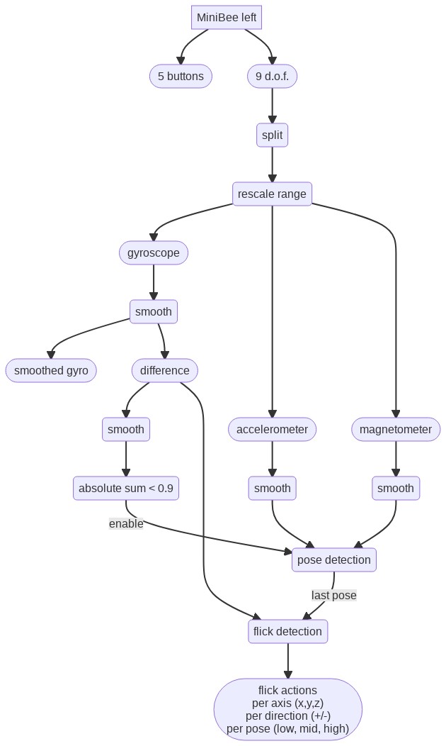
Preprocessing of data
To preprocess the data from the gyroscope, accelerometer and magnetometer, I first split the data into these three different streams (each having 3 axes), and do a range mapping with a bipolar spec: that is I am using a non-linear mapping from the integer input data range, to a range between -1 and 1, in such a way that the middle point is at 0, and the resulting range feels linear with regard to the movements I make.
The for each of the three, I apply a exponential smoothing filter. In certain cases I use the difference output of this filter: the raw input value minus the smoothed filter output. This difference output is then processed with another exponential smoothing filter. In some cases this second filter has another parameter for the signal becoming larger, versus the signal becoming smaller.
Poses and flicks
To start and stop sounds, I am using a combination of flick detection and pose detection.
The pose selects the instrument that will be triggered. The pose detection algorithm makes use of prerecorded data of three different poses. The continuous smoothed data from the accelerometer and magnetometer is compared with the mean of the prerecorded data to determine whether the current value is within an factor of measured variation of the prerecorded samples. If that is the case, the pose is matched.
The flick detection makes use of the difference of the gyroscope data with its smoothed version. If this difference crosses a certain threshold, an action is performed. Different thresholds can be set for different axes and different directions of the data. The detected pose is used as additional data to determine the action to trigger.
To avoid that movement to flick affects the pose detection, the pose detection is only enabled when the summed smoothed difference signal of the gyroscope data is below a certain value.
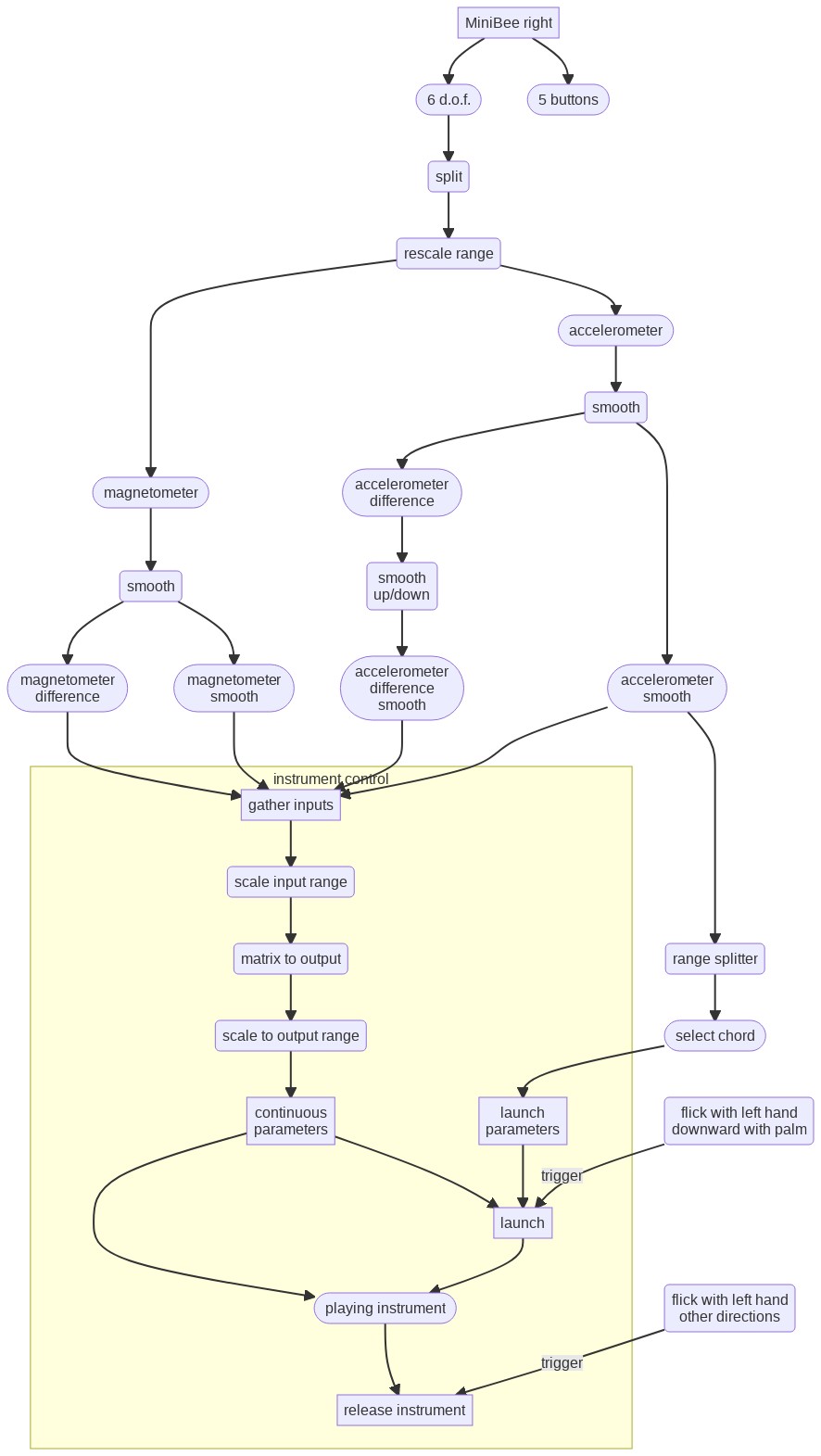
Instrument launching and control
Instruments are started, or launched, with flicks of the left hand when the palm of the hand is moved downwards (if you look at the arm held horizontally forwards with the back of the hand pointing up). Other flicks (upward, and those rolling the wrist to left or right) stop the instrument again.
The right hand data is used to control the different parameters of the sound:
- The position of the right hand when a sound is started selects a chord (a set of multiplication factors for the frequency of the sound) with which an instrument is started. This chord cannot be changed after launch.
- The movement of the right hand then controls different parameters continuously as long as the sound is playing.
The input for control are both the smoothed and the difference with the smoothed data from the accelerometer and the magnetometer.
For each instrument there are differences in how exactly the different parameters affect the sound. Some concepts that prevail are:
- smoothed values are used for frequency, filter frequency, pulse width, and panning position.
- difference values are used for amplitude and filter resonance.
Lick recording and playback
The buttons on both gloves are used to control the Lick Machine.
While the thumb button on the right hand glove is pressed, the data that is used for instrument control and the output data from the flick detector and the pose detector (at the moment of flicking) is recorded into a lick buffer. This happens as long as the button is pressed. At a button press, the buffer is first cleared and then recorded into. The data is always recorded into the current lick buffer.
In total there are 16 lick buffers. With the ring and pink buttons of the right glove the current lick buffer can be changed.
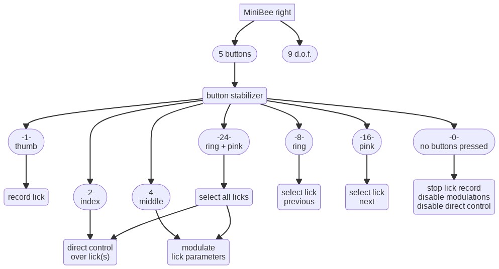
When the thumb button on the left hand glove is pressed flicks with the left hand trigger playback of licks, rather than instruments. The pose and flick axis and direction determines which lick will be playing back. When also the index button of the left glove is pressed, the lick will play in looped mode, otherwise it will just play once and stop.
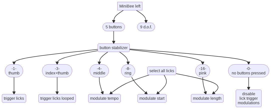
Lick modulation
The playback of the licks can then be modulated:
- the index finger of the right glove: enables replacing the recorded data with the current data from the right hands’ accelerometer and magnetometer.
- the middle finger of the right glove: enables controlling additional paramaters of the sound with data from the right hands’ accelerometer and magnetometer.
- the middle finger of the left glove: enables changing the tempo of playback with an up and down movement of the right arm.
- the ring finger of the left glove: enables changing the start position in the lick buffer by rolling the right arm.
- the little finger of the left glove: enables changing the playback length of the lick buffer by rolling the right arm.
When these three left glove buttons are pressed simultaneously, all three parameters are modulated at the same time.
The modulation only takes effect on the currently selected lick. If both ring and pink buttons of the right glove are pressed, the modulation affects all licks simultaneously.
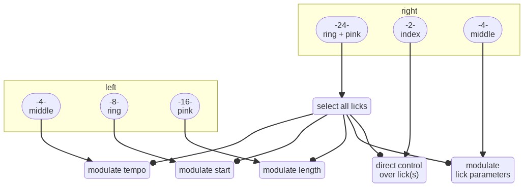
Flowchart images created with the Mermaid live editor
-
Interview at The Aesthetics of Creative Coding
On June 30, an interview with me will appear in the “Behind the screens”-series on the Medium-blog The Aesthetics of Creative Coding.
In the interview I’m reflecting on my history with livecoding, discuss code as an interface, and the various projects that relate to livecoding.
-
Just a question of mapping tour to Norway
Currently I am on a tour to Norway, as part of my book project “Just a question of mapping”. I’m traveling by train, so I also made stops in Aabenraa (visiting Nina Essendrop) and Copenhagen, and will make a stop also in Malmö. Details of the full tour are on the book project site, and I am also making blog posts there on the progress, both of the tour and of the book research and writing.
And it seems out of the work on the book, at least one new performance will evolve: a lecture performance on mapping. At the Faculty of Senses presentation in Copenhagen I performed a first version of this, and it’s likely that this will evolve further.
-
Article on Fair Practice at PlatformBK
Over the past years a Fair Practice Code has been developed in the arts sector in the Netherlands, after realising the precarious situation of artists - both financially and in terms of power of negotiation. For the upcoming round of four year funding for institutions, adherence to this code is one of the requirements to get funding. But looking in detail at how a city like Den Haag includes questions about the Fair Practice Code there is still reason to be concerned. In reaction, I wrote the article “Als Fair Practice Code het antwoord is, wilt u dan de vraag nog eens herhalen?” (if fair practice code is the answer, could you repeat the question perhaps?). An English translation will follow later in the month.
-
Tinnitus highlighted by IMPAKT
IMPAKT highlighted an old piece I made in 2011, for the Inclusive Extensions - shifting borders by design project.
Tinnitus: A work by Marije Baalman and Mariagiovanna Nuzzi
When it comes to hearing disabilities, Tinnitus might be one of the most common. In the Netherlands alone, an estimated 2 million people suffer from Tinnitus. It is a form of hearing damage, in which you continuously experience sound, even when there is no external sound. Tinnitus has many different causes, but the most common cause is (over)exposure to loud noise.
The tone people hear can vary from beeping sounds and flute tones to whizzing and crackling. Every form of Tinnitus is unique. People who have Tinnitus experience the sound they hear non-stop. In most cases, the sound is not only non-stop, but also predominant, even in the presence of external sound. As a side effect, people with Tinnitus often suffer from psychological issues as well.
In 2011, Marije Baalman and Mariagiovanna Nuzzi created a project called Tinnitus, or My little acufene. Baalman describes the work as a half an hour composition exploring the sound world of people with hearing disorders. The sound design in the piece is based on an interview with someone who suffers from tinnitus, describing the sound to Baalman and comparing it to the synthesized sound that Baalman has created. The person also discusses the social and psychological consequences of suffering from hearing loss and hearing a ringing sound all the time.
The public can hear the sound, but the interviewed person can only partly hear the sound. This is due to the fact that Tinnitus is a hearing perception produced by the brain itself in order to compensate for the damaged part, which is the sound frequency the sufferer misses.
Tinnitus is often a lonely disease, because one cannot see that someone suffers from it on the outside. What makes it even more difficult for sufferers, is that Tinnitus is uncurable. People with Tinnitus have to deal with hearing sound all the time. This is why Baalman’s work is an interesting piece: it gives the listener a look into the world of someone who suffers from Tinnitus, a glimpse into what it is like to have this kind of hearing damage.
-
Livecoding with one hand
I’m typing this post with the Twiddler (well, I started at least). I’ve been practising now for some months and developing the interface for ‘Etudes pour le livecoding a une main’, basically since the notification came in that the performance got accepted for the ICLC.
Backups
An important thing I got reminded of, it how important it is to have backups of your device. On January 2nd my Twiddler broke down… One of the keys was not working anymore. So I had to order a new one, which with some delay from UPS came in still in time. On the forum I had read I can get them with the back not glued on, so that in the future I can repair the Twiddler myself. The broken one I can send in to be repaired. So I’m happy about the customer service. And once the broken one comes back repaired I will have two Twiddlers available.
In the meantime, I also started on a DIY version, using a MiniBee. It’s mostly working, but the timing for detecting the chords still needs some tuning. Developing the algorithm for that has been quite interesting though: when do you detect that something is a chord? When do you send out the ‘chord-down’ press, when the ‘repeat’, and when the ‘up’. And how do you transition from one to the other? Some advantages of building it yourself are that you can really shape the device according to your own hand. That is quite promising for the future. On the other hand, the buttons will need some sort of caps to feel nice to type on. So - a promising development, but still some work to do.
The coding interface subsequently had to be adapted to accept either the keyboard input, or the MiniBee input, which was a good reason to disentangle the GUI from the model of the tutor a bit more.
Creating an editor
While developing the interface for the performance, I realised that to speed up the actual performance, I would need to be able to edit previously typed code. So I made options to browse the evaluated code, copy blocks to the ‘typed code’ view, and then cut lines from that, paste them elsewhere, insert lines, and select a line to edit. At some moment it felt like re-writing
vi.The other challenge there was to navigate through the edited line. Moving the cursor single steps is easy, making it jump in sensible ways was a bit more tricky, but more or less works now. One improvement I wish for is still to not jump to
.within a number, but only to.that separate a variable (or Class) and method. That is for later.The current version is like this: the extension to the
String-class:+ String { findOneOf{ arg strings, ignoreCase=false, offset = 0; var res; res = strings.collect{ |c| this.find( c, ignoreCase, offset ); }.select{ |it| it.notNil }; if ( res.notNil ){ res = res.minItem; }; ^res; } findOneOfBackwards{ arg strings, ignoreCase=false, offset = 0x7FFFFFFE; var res; res = strings.collect{ |c| this.findBackwards( c, ignoreCase, offset ); }.select{ |it| it.notNil }; if ( res.notNil ){ res = res.maxItem; }; ^res; } }And using it like this in the Tutor:
	jumpForwardCursorPosition{
		// var curChar = currentLineTyped.at( cursorPosition );
		var stringsToFind = [".", "," , "(", " ", ")" ];
		//.select{ |it| it != curChar };
		var newpos = currentLineTyped.findOneOf( stringsToFind, false, cursorPosition+1 );
		if ( newpos.notNil ){
			this.setCursorPosition( newpos );
			^true;
		}{
			// nil, but do jump a bit
			this.setCursorPosition( cursorPosition + 5 );
			^true;
		};
		^false;
	}

	jumpBackwardCursorPosition{
		// var curChar = currentLineTyped.at( cursorPosition );
		var stringsToFind = [".", "," , "(", " ", ")" ];
		// .select{ |it| it != curChar };
		var newpos = currentLineTyped.findOneOfBackwards( stringsToFind, false, cursorPosition-1 );
		if ( newpos.notNil ){
			this.setCursorPosition( newpos );
			^true;
		}{
			// nil, but do jump a bit
			this.setCursorPosition( cursorPosition - 5 );
			^true;
		};
		^false;
	}
And then: a blinking cursor! The SuperCollider GUI interface does not let you control the cursor position in a TextField or TextView. But TextView allowed me to control the color and font of selections of the text. So I now have a really nice red blinking cursor.
	cursorBlinkOn = cursorBlinkOn + 1;
	if ( cursorBlinkOn > 6 ){
		if ( tutor.cursorPosition == tutor.currentLineTyped.size ){
			typing.setString( "_", tutor.currentLineTyped.size, 1 );
		}{
			if ( tutor.currentLineTyped.at( tutor.cursorPosition ).isSpace ){
				typing.setString( "_", tutor.cursorPosition, 1 );
			};
		};
		typing.setStringColor( Color.red, tutor.cursorPosition, 1 );
	};
	if ( cursorBlinkOn > 12 ){
		cursorBlinkOn = 0;
		typing.setStringColor( Color.black, tutor.cursorPosition, 1 );
	};
	typing.setFont( blinkFont, tutor.cursorPosition, 1 );
Rehearsals
Rehearsing the piece, I realise that I am still half as fast as Redfrik’s original performance. Going through the piece, I am wondering also in how far can I change the original? I already had to adapt some things to ensure that the piece would run under current SuperCollider versions, and to ensure that the length of the lines fitted in the Tutor.
But Redfrik also made a mistake during the performance, as he writes on his website: “it’s a bit embarrassing if you study it more carefully. the use of ~pub near the end is a big mistake for instance. i meant ~out and i don’t know what i was thinking there…” The mistake had a big influence on the following lines of code he executed, as he was trying to figure out what went wrong. Should I correct the mistake when I reperform the piece?
Dramatical effects
To add to the dramaturgy of the performance and create a kind of ‘classical instrumentalist impression’, I got myself a music stand to put my laptop on, and I’ll put my sound card and DMX controller at the foot of that stand. I’ll sit on a chair a short distance behind the music stand. And I’ll dress up nicely with a jacket.
Also I’ve added DMX RGB lights so that my actions on the typing will be reflected in the color:
- green for a correctly typed character
- red fro a wrongly typed character
- blue for navigation characters
- lila for a mode change of the editor
- yellow for correctly evaluated code
- orange for wrong evaluated code
-
Creating Algorithmic Sentience
In the second part of my “Sentient Machines” residency at Baltan Laboratories, I focused on prototyping the game interactions for the multiparticipant environment. During the residency I worked with Tim Bosje and Marion Traenkle.
We did a playtest on June 6 with 7 participants. As we had to put out the call for the playtest long before we created the larp/game, I gave the name Algorithmic Sentience to the larp in reference to the name of the residency program at Baltan: Sentient Machines, and highlighting the focus for the game: exploring both how algorithms change our ‘sentience’ as well as posing the question whether there is a ‘sentience’ of the algorithms.
In this report, I reflect on the design process, the playtest and the feedback, and what we want to change before the next playtest.
the announcement
Sentience is the capacity to feel, perceive or experience subjectively. Algorithmic sentience is a physical game or larp that explores how algorithms may influence our perception of the world. What senses does an algorithm have? What decisions do we let the algorithm take? How are these decisions executed? How do these decisions affect our experience of the world and our relationship with each other? What is our relationship to the algorithms? Participants in the larp will play humans or algorithms. The interactions between them will be governed by metatechniques/game mechanics that simulate how future technologies may mediate our senses.
designing the game/larp
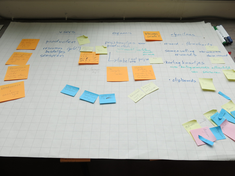
To design the game/larp, I first sat together with Tim Bosje for two days to discuss the various elements that should be part of the game. This resulted in lots of post-its and a number of large flipover sheets of texts.
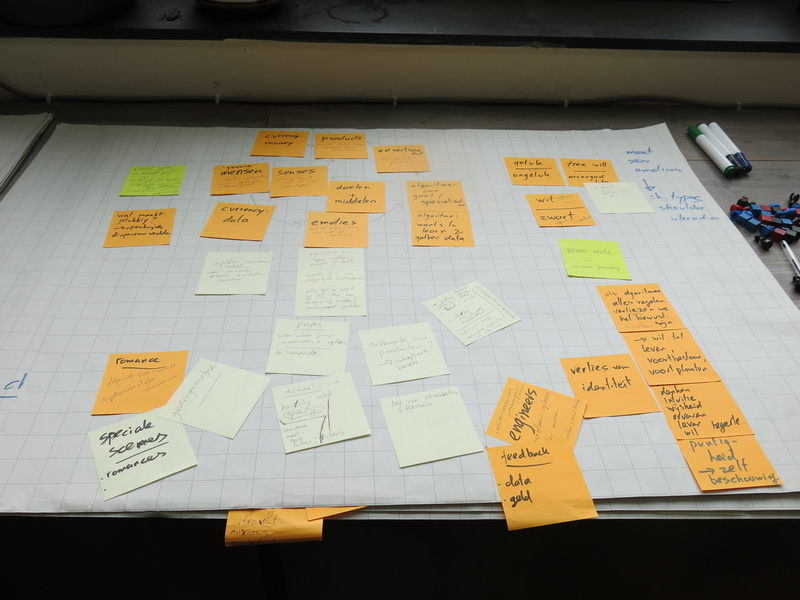
Gathering first concepts.The main theme emerged from our gathering of ideas: a simulation game that shows how our choices for products are more and more influenced by algorithms that act on our data. An important factor in this is also that there are limited resources available to buy products, and that often the choice to provide data (e.g. by sharing on social media, getting a customer card) is motivated by offering discounts or bonuses, and ‘being able to provide you with customised offers’.
character types or roles
We wanted to look at the interaction between three different roles in this process:
Different character types in the game.- users - people living their lives in the world and having certain needs they need to fulfill during their lives. They have preferences for certain products, a limited amount of resources to obtain these products and a personality.
- engineers - are people who like to solve problems in the world. They are clever people, who know how to program, who design agents, and who are paid by companies to find ways to sell their products best. They also have a personality.
- agents (or algorithms, we renamed the character type at some point in the development) - created by the engineers to solve a class of problems. They can perform calculation, data processing and automated reasoning tasks. They will observe the users and based on the instructions for dealing with the data from their observations, they will influence the users to make the best choice in products.
Within the game one engineer would design one agent who would interact with one user, so there were teams of three in a sense. The users and engineers could interact with each other as well, but not the agents (apart from the sharing phase).
game flow
The game takes place in three different eras: three different time periods in the user’s lives, where algorithms will take more and more influence on their lives. Between these different eras, the users will have chosen certain sensors that will give the agent more information to better help the user and make the user happier in life. And of course, there would be inflation between the eras: product costs would go up.
Within each era, there are different phases that will be repeated three times within the era:
- Choosing: here the user, helped by the agent, will choose a product.
- Sharing: the user is given the option to share information about their choice and how they feel about it. The agent will show what is shared to other users, who may react on it.
- Moving in the world: here the users will move around in the world (the open space we have created) and the users can interact with each other through touching on the shoulder. In the meantime the agent reports back to the engineer with the data that is gathered and how the agent has performed. The engineer may then make improvements to the agent.
reinforcement learning
For the agents, I decided to focus on the concept of reinforcement learning, which is an approach from AI (artificial intelligence) computing that is quite commonly used, and which also gives the agent some freedom in choosing actions to take. In other words: it seemed performable by human players.
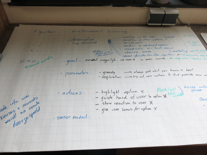
Reinforcement learning within the game.The basic concept is that an agent with reinforcement learning can take actions in an environment, and then observe that environment. The engineer designing the algorithm determines how much reward the agent gets for certain observations. The agent can then explore the reward gained for the different actions and try to maximise the total reward gained. The agent can be explorative: try unexplored actions to see if they give a high reward, or be greedy: stick to already explored actions that the agent knows will yield a high reward.
space and light design
The initial idea we had for the space was to have three or four (depending on the amount of players) different stations where the users would make a choice guided by the agent. Then the space in the middle would be used to move around in the world.
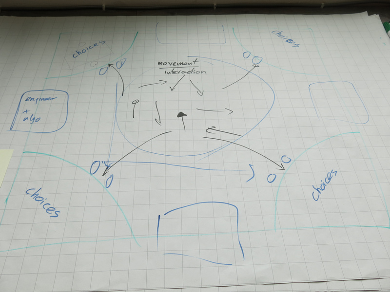
Initial space concept.Discussing with Marion and looking at the spatial layout of the space we had available at Baltan Laboratories, we adapted the spatial layout into three zones:
- the moving area, where the users would interact with each other)
- the choosing area, where the users would each interact with their agent. From this area the agents would also be able to observe the users in the moving area.
- the engineer area, where the engineers would interact with each other. The agents would move between the choosing area and the engineer area. The engineers would be with their back to the other areas.
By separating the areas in this way, there would be a clear choreography for the different characters.
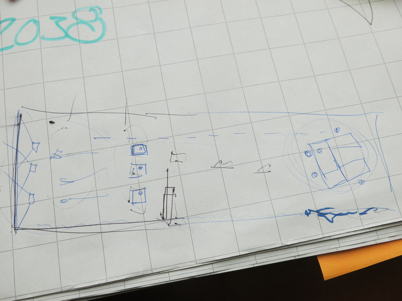
Final space concept for the Baltan Laboratories space setup.For the light design, we chose to use RGB led pars to shine on the white back wall of the space (which is normally used for projections). Shining light on this white wall, gave enough reflection into the space to give an athmosphere to the moving area.
The light is used in the game to reflect the most common emotion of the users: so we had different light patterns with changing color and intensity, designed for the three emotions: happy, sad and angry. Similarly, we had musical melodies for each of these emotions, which would be played during the moving phase.
playing the game
We first introduced the players into the game through a workshop. In this way we introduced the different types of characters, the game flow and the mechanics used in the game to simulate interactions through technology.
movement and touch
Within the game we use movement and touch as a way to express how the users feel. Within the workshop, this was one of the first exercises to let the players loosen up and at the same time prepare the movements and touch interactions they would have during the game.
After the movements were made, we asked each of them to analyse their own movements and touch interactions to classify them using our sensor simulation.
The motion sensor would be able to detect two features: whether a movement was linear and circular and had a low or high intensity. By distinguishing these features, a unique combination would allow a classification to map to the emotion the movement signified. Later on in the workshop, the engineers would use the data set gathered from this analysis to build the algorithm for movement classification that the agents would use.
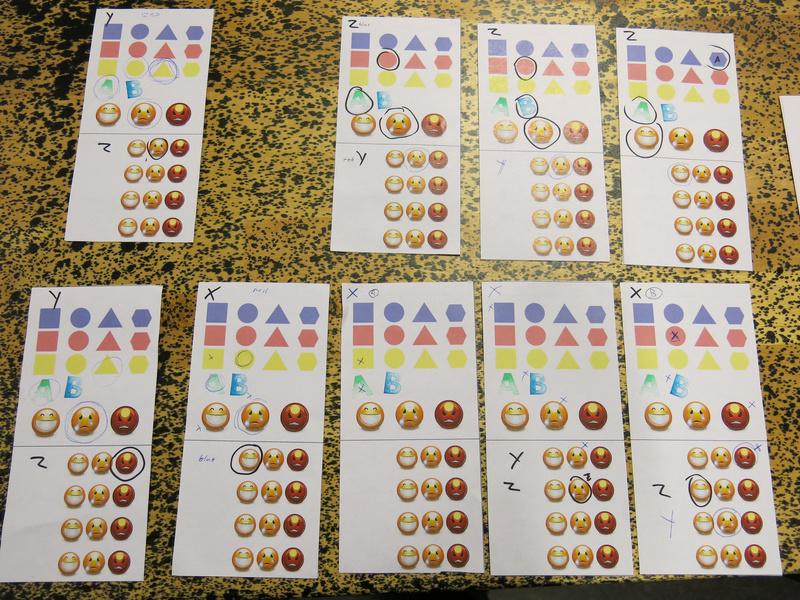
After the game I analysed the different movement algorithms and summarised the results (see the image below). What is interesting in the result is that the different players agreed on how intensity of the movement matched emotions, but that there were slight differences in the linear or circular features, although there was a clear majority for certain types as well. During the movement exercise, we encouraged the players to create their own movement, but of course, people did copy each other’s movements as well. And of course, there is body language (culturally defined) that also plays a role in the choices the players made in their movement creation.
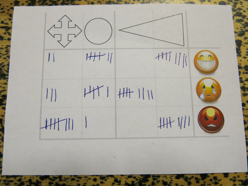
Summarised algorithm for the movement classification.For the touch: we limited the touch interaction to be on the shoulder. We indicated to the players that that was where the sensor would be. This was inspired by the touch garment made during the first residency.
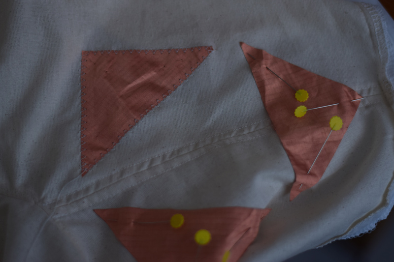
The simulated sensor would be able to detect the location of the touch (at the back, front and/or side of the shoulder) and the intensity. The players could draw the location in a prepared sheet. The intensity indication was the same as for the movement.
Again, after the game, I summarised the results; it was a bit hard to ‘count’ the location, but I just was drawing more often on the same location if a location was present more often. In the image below: the top triangle is the back of the shoulder, and the bottom triangle the front of the shoulder. What is interesting to see in the summary is again that the intensity is fairly consistent, but the location varies quite a bit.
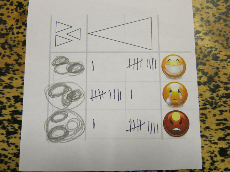
Summarised algorithm for the touch classification.The aim for designing the algorithms in this way for the game, was to give the players a sense of how engineers deal with training data in the design of an algorithm. They have a limited set of test data (each engineer only got two or three of these analysis cards to work with), may use their own assumptions (the engineer players also took part in the exercise), and do not necessarily know what exactly the data represents in the real world (the engineers had no accompanying video recording of the movement and they did not know who of the other players made the movement that the analysis corresponded with).
In the further development of the project, I might use some of the results of these movement creations and analysis to train the algorithms that are used on the actual sensors. From the data gathered, it seems that there is a quite a bit of correlation between the features the sensors detected and the classification. Of course, as with a lot of gesture classification algorithms: the algorithm does not account for the fact that there may be other movements and touch interactions that also fit these features, but do not correspond to the classified emotion.
character creation
Within the game, the products were abstract things with three different features: color, shape and a stamp A or B.
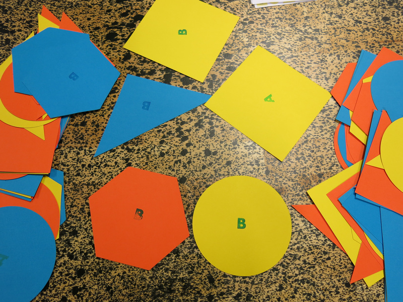
The different types of products in the game.The users would pick a product preference, by drawing three cards: one for the shape, one for the color and one for product type A or B. If all three features would match for the product they would choose, they would be most excited, if none matched, they would not be excited at all. It was up to the player to determine what emotion their excitement about their choice would match.
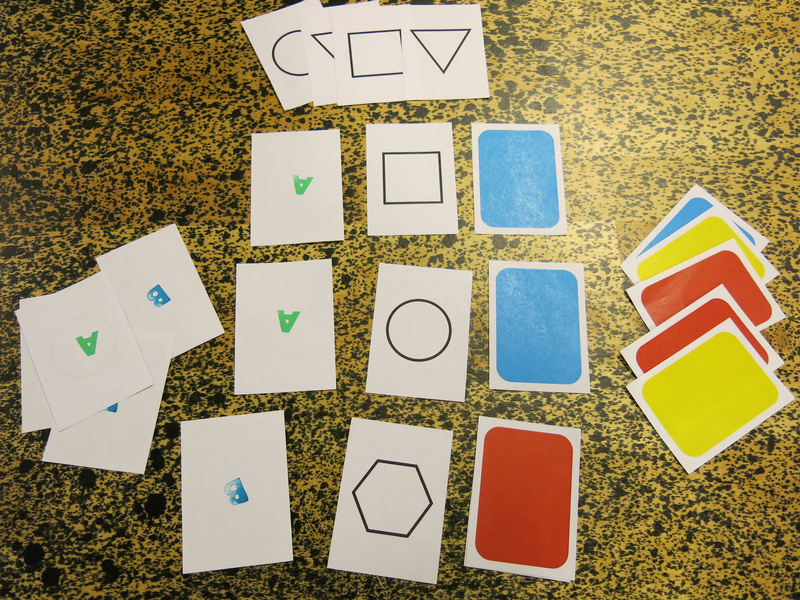
The product preference cards.In addition to their product preference, they would also have a personality trait, that would suggest another hint on how to play the character, e.g. how willing she would be to embrace new technologies, to share her feelings or to spend resources.
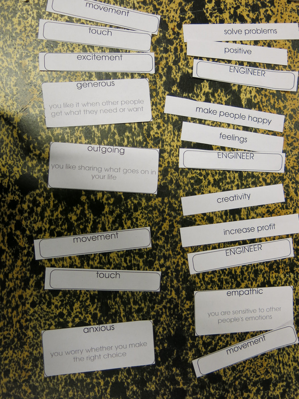
The different personality traits of the users and engineers. Also shown are the sensors that the users chose between the two eras.The engineers also had personality traits, they had a drive: their motivation as an engineer, and a way of discussing, inspired by the theory of the six thinking hats of Edward De Bono.
The main task for the engineers was to design the agents’ reinforcement learning algorithm. For this we had created a flow chart in which they could assign reward points to different observed parameters. The idea was that for each possible emotion as a result of a product chosen, the engineer would assign points, and the agent would fill in the flowchart during the phases to determine the reward gained for a certain action to push the user to make a certain choice. The actions the agent could take were different ways of influencing the users’ choice: highlighting a certain choice with the light on the choosing table, giving a discount on a product, or hiding the other products. Using these actions would have a negative reward.
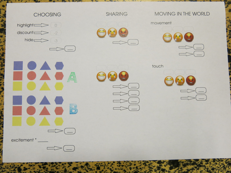
The flowchart used by the engineers and agents.What proved difficult was the amount of things to fill in for the engineer all at once. Feedback from the players was to build it up more during the game, adding things with each era, and add more description to the sheet, rather than just having the images. Another idea that came up was to distribute the sheet more between the agents and engineers: that the agents would just do the observations and fill in a form according to that, and that they would then go to the engineer who would then give them the reward for the choice they made.
Also, awarding points for the products that were chosen could be made simpler, by just giving points per feature, rather than per product.
That would make the role of the agent a bit easier and the role of the engineer a bit more important during the game. The agent could then still use the sheet for recording what reward to expect for which user choice.
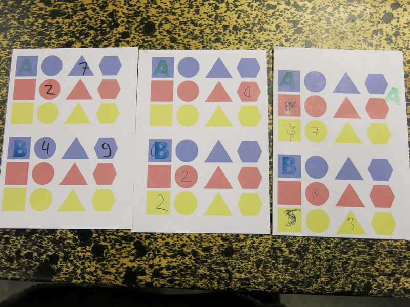
The sheet for the agent to track the rewards for particular choices.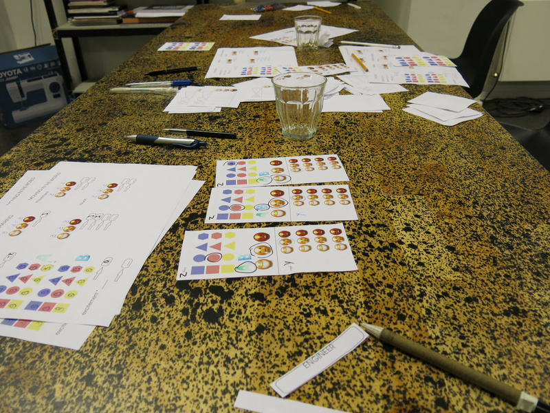
The engineer table after the game, filled with data sheets and previous versions of the flowchart.social media interaction
Social media interactions were simulated with a sheet, where the user’s choice was indicated, and the user could then point to the emotion she was feeling. The agent would then give the sheet to the other agents, who would let their user react on the choice.
The social media sharing sheets of the game.During the playtest we ran out of sharing sheets (due to a miscalculation of how many to print) and Tim suggested to use a more physical way of sharing the choice: standing on a chair in the middle of the world and expression the emotion in movement while showing the choice made. This was a very interesting direction to take: it makes the act of sharing very theatrical, and is a nice commentary on the exhibitionism of sharing on social media.
reflection
After the playtest we had a discussion with the players on what they experienced during the game and what aspects could be changed or improved. Marion, Tim and me had a discussion afterwards as well to discuss future directions.
Some of this feedback on the game design elements is already mentioned in the text above, I will continue in more detail here.
physical and verbal interaction
One of the first aspects to look at is to make the game more physical and theatrical: right now the game uses a lot of elements which are a lot like board game mechanisms (using the paper sheets). A first step was to make the social media interaction more theatrical. So next, we need to figure out which other elements we can make more physical.
Originally I imagined the interaction between the agents and users to be completely non-verbal. As we did not explicitly mention this in the introduction, the interaction turned out to be much more verbal and the software agents became more like sales agents. In a sense, this is a parallel that is quite fitting. Also the interaction between the engineer and agent became much more verbal than I expected.
the role of the agents
The agents are the connection between the engineers and the users, so they play an important role in the game.
One of the players described how she played the agent, really analysing the movement and touch interaction based on the features we defined for the classification algorithms. It was important here to unlearn the human ability to read body language and to not look at facial expressions. This aspect of playing the agent can be stressed more during the preparation workshop. It might also help (as mentioned above) to change the flowchart sheet and instead give the agents an observation list, which is then evaluated by the engineers. Then the agents can focus on the observation of the movement and touch interaction, without giving an interpretation to it. Also the reward could be made more physical to also use game tokens for these, so the reward for the agents would also be more tangible.
Another suggestion was to remove the distinct phases (choosing, sharing, moving) and instead have the agents mingle with the users and explicitly offer them products, seduce them to make choices. The engineers would then give the agents more explicitly products to sell. Agents would then also interact with multiple users and the agent + engineer team would try to optimise their profit. The role of the agent would then even more explicitly be similar to a sales agent. I also like the image of an agent with a flipchart filling in observations.
role of the engineers
The role of the engineers was most removed from the user experience, which was intended for the game. A suggestion of one of the players was to allow the engineers at least during the ‘test round’ to see what is going on in the world, so they would have some idea. This could be explained within the fiction of the game as a kind of ‘user testing’ phase which is common in engineering.
The link between the products that were sold and which products to push - a factor that would be determined by the advertisers hiring the engineers - was not worked out well enough yet before the playtest. Before the next playtest we will need to make this factor more explicit, so that the engineers have some way of knowing that they are doing well, and also give them an extrinsic force against which they have to make decisions.
The selection of products to sell could also be determined by the engineers, so they would have more direct influence on what the users could choose from. Now the product selection was too limited and the engineers did not know what the available choices were, which resulted in the engineers having too little information to base their evaluation of the agent’s performance on.
Besides the data provided by the agent, also the verbal feedback from the agents was found useful for the engineers to make their decisions, as it gave a bit more clear idea of what was going on in the world.
What the engineers did find out during the game, was that the users had a clear preference for products with the letter “A” on it.
learning the game
A handout for players with an overview of the game would be useful, so the players do not have to rely on just the verbal instructions given during the preparation workshop.
game flow
On a practical level the game flow was a bit hard; the players could not distinguish clearly enough between the sounds of the different phases, and for myself controlling the sound, it was also hard to time the sounds, as I had trouble figuring out from a distance how far players were. Having a clearer idea of how long each phase should be, would have improved this, and also training the players more in recognising the sounds so they would feel the time pressure of each phase. I also imagined the moving phase to last a bit longer than that the users actually needed to move around.
Above it was suggested to change the game flow and rather than using phases, they could be mixed. Then the agents would move between the users to seduce them to buy products. The users would have a minimum amount of products they would need to buy during each era, but could buy more. The agents could then also use a larger variety of actions to seduce the users, and more products could be bought during each era (which in turn would increase the amount of data gathered by the agents and make the influence they can have larger).
Perhaps it is an idea that the users interact non-verbally, using the movement and touch interactions that are designed, but that the agents can whisper to the users to seduce them.
tensions for each role
Finally, what we need to carefully think about is how to make the tensions for each of the roles more explicitly present in the game.
For the user there is the tension between having a free choice and being forced to give up data to be able to obtain the needed products and getting less choice over time.
For the engineer it is the tension between making profit (to survive as a company) and the drive to make the world a happier place. Happiness vs. profit - and can they coexist?
For the agent, the influence of the reward should be made more important. Perhaps there is a performance measurement that the engineer uses, and if the agent does not perform well enough they will be discarded, or reprogrammed to such an extent that they are no longer themselves. How many modifications can be made to a software agent before it looses its identity?
credits
In our game materials we used emoticons from the GNOME-icon-theme (version 3) created by GNOME icon artists. These emoticons are licensed with the Creative Commons Attribution-Share Alike 3.0 Unported license.
The game materials were created using the libre, open source desktop publishing program Scribus. Some of the default shapes from the program are used in the game materials.
-
More images from Baltan
Some more pictures from the residency at Baltan Laboratories of the work in progress.
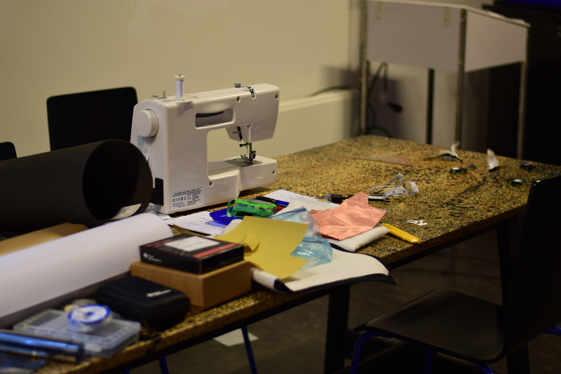
The workdesk at Baltan (photos by Tineke van Hilten)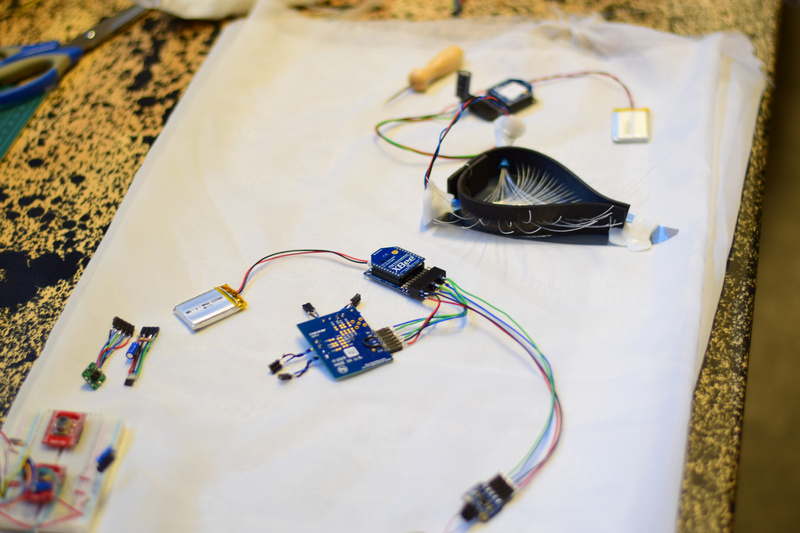
Sensors and in particular the Eye (photos by Tineke van Hilten)
Preparing the capacitive sensors on the shoulders (photos by Tineke van Hilten)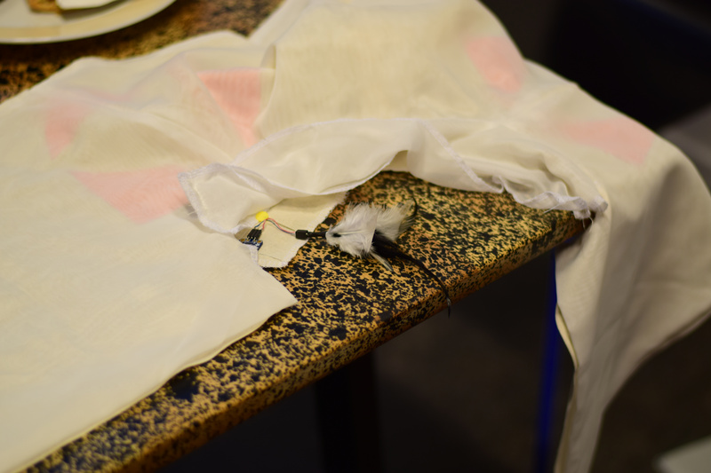
Placing the ticklers (photos by Tineke van Hilten)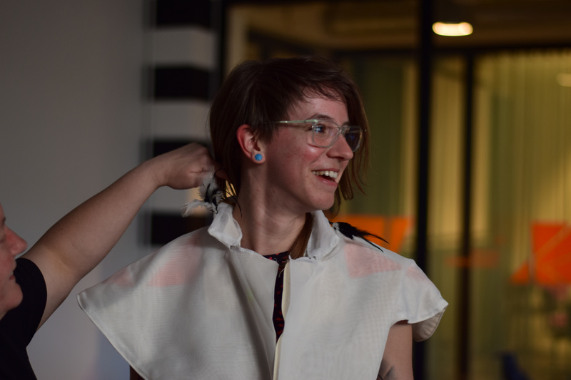
The touch garment in action (photos by Tineke van Hilten)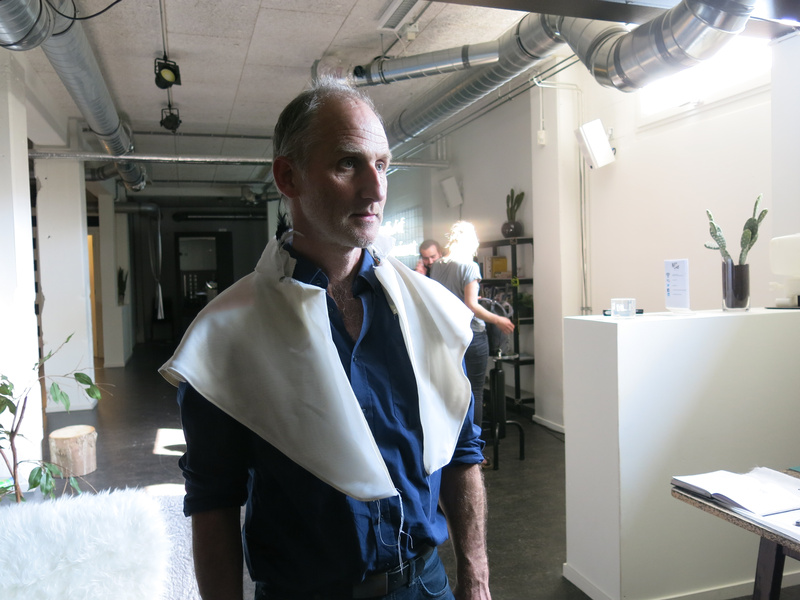
The touch garment in action (photos by Marije Baalman)
-
Building prototypes at Baltan
In the first part of my “Sentient Machines” residency at Baltan Laboratories, I focused on building first versions of the different protheses prototypes to use in the Malbody Centre project. During this residency Tineke van Hilten joined me to help out with creating a wearable.
In this report, I address the various things that I worked on by theme, rather than in chronological order.
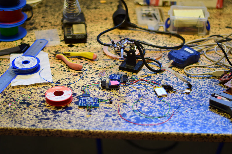
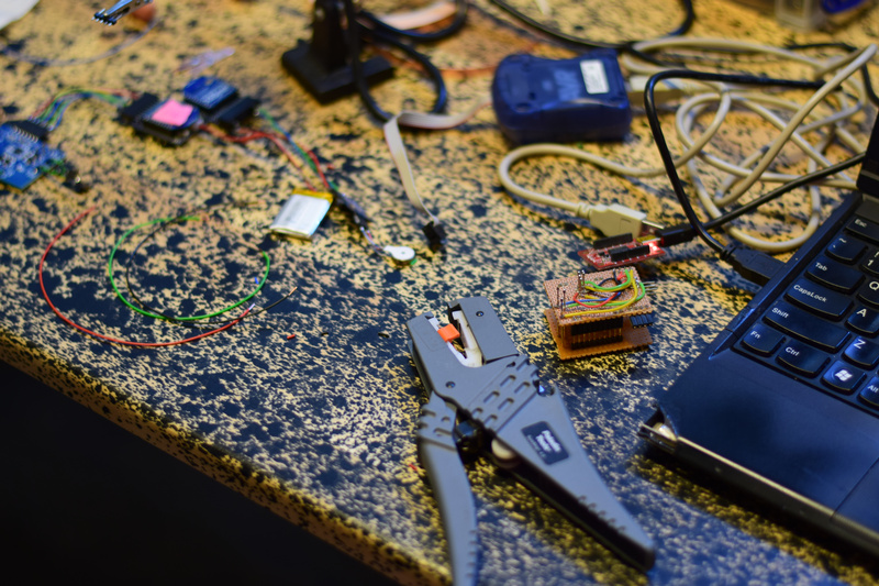
my worktable at Baltan and the different elements I madeBiometric sensing
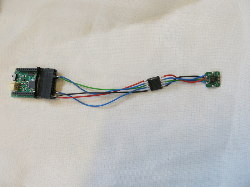
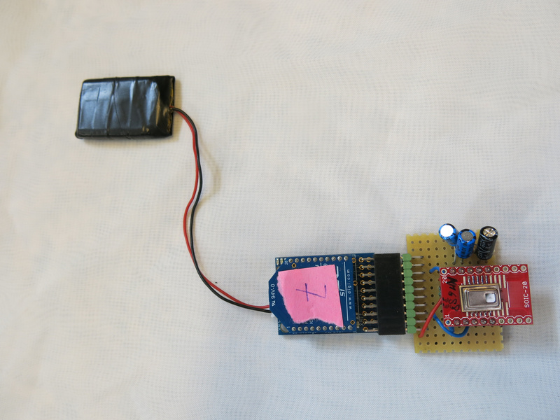
For biometric sensing, I wanted to try out how to detect breathing and heart rate. For this I got two sensors: a humidity/temperature sensor (a HIH8000 series sensor from Honeywell) and an optical sensor based on a reference design for pulse measurement (the MAX30101 from Maxim).
During the residency I got both of these to work with the Sense/Stage MiniBee to get the data wireless to my computer. I did some very basic tests looking at the data to get a sense whether breath and heartrate could be detected and measured with them.
Breath
With the humidity/temperature sensor I got quite nice results holding the sensor in front of my mouth or in front of my nose. Both temperature and humidity values are fluctuating nicely along with my breath. Humidity occasionally has a shift in overall level when the breathing rhythm is changed, so to make a good measurement of the rhythm, I will need to do some filtering to only look at the fluctuation of the breathing. The data looks promising, so the next step is to figure out how to make something in front of the mouth/nose to mount the sensor. I also would like to combine this sensor with one or two small microphones as an additional way of measuring the air flow and possibly sounds that are uttered by the wearer. And maybe, there should also be a speaker to replace these sounds with something controlled algorithmically.
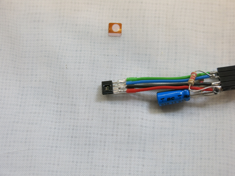
the humidity sensor hooked up to the MiniBeeHeartrate
For the heartrate: I got the sensor working and used the algorithm that was provided in example libraries to detect the peaks in the measured signal. While this works fairly well, occasionally a beat is missed or a second peak is detected. That means that either the peak detection algorithm needs to be improved, or I just need to filter a bit for these errors. In terms of placement, I had the impression that placing the sensor on the earlobe is more reliable than placing it on a fingertip. Possibly there are other parts of the body that may work well.
the pulse sensor hooked up to the MiniBeeVision
For the vision I worked both on the sensor: how the prothesis will see things, as well as how the vision would be altered and mediated.
Thermal vision
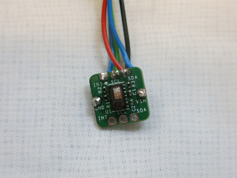
For sensing vision, I decided not to use a camera, but instead use a more low resolution sensor. I found a thermal sensor (the AMG88xx) that senses the temperature variations in an 8x8 grid. It does this with quite a good resolution: 0.25 degrees Celsius resolution. From each of the 64 pixels a 16-bit value is obtained from the sensor. To make this work well with sending out the data wireless, I had to package the result in blocks of 16 pixel values as otherwise the package to be sent wireless got too big. But still with this approach I can get an update rate of 20 Hz, which is fast enough for the sensor.
thermal 8x8 grid sensor hooked up to the MiniBeeBlocking vision
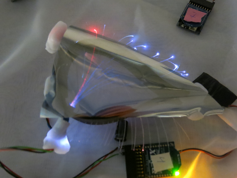
To block or let through vision, I had one idea that needed to be tested. I had made a hood, which would cover the head. Inside the hood I attached some LEDs and held a foil in front of my eyes that would either be see through or mirror depending on which side there is more light coming in. This didn’t work as well as I hoped, using multiple layers increased the effect a bit, but that did make it rather dark. So experiment failed.
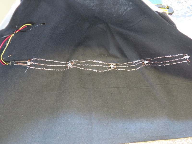
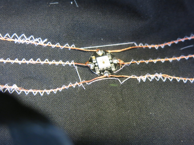
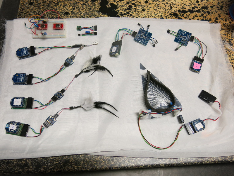
LEDs sewn into the hoodThe next test was to see what would happen if I used fiberglass wires for conducting light. This idea came from looking at fabrics that can light up, which also use fiberglass wires. As I didn’t manage to obtain a piece of this fabric, but had a roll of fiberglass wire with me, I decided to make something from these.
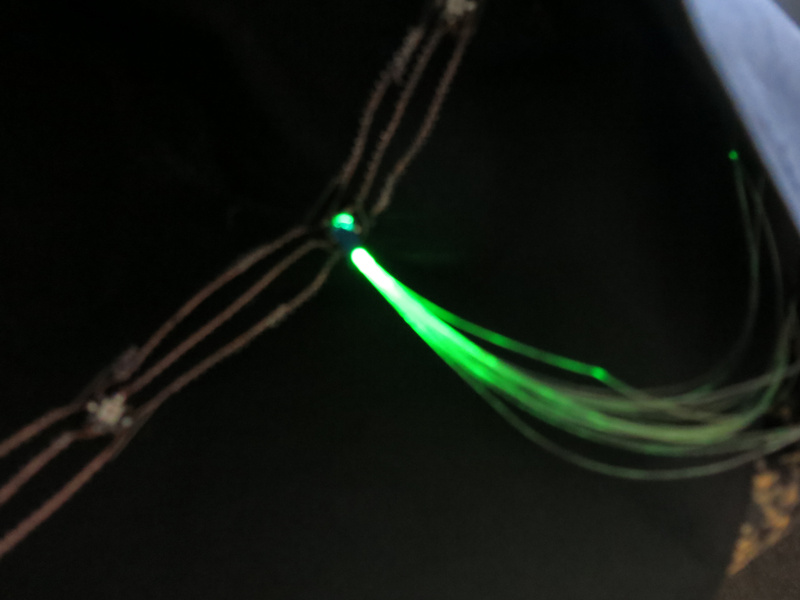
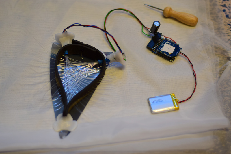
testing fiberglass wires on the LEDAfter an initial test to see whether I could get an LED to light up the fiberglass wire, I did some simple tests to see what this would look like when up close to my eyes. The idea seemed promising. Tineke suggested to make a kind of frame for the eye, to hold the fiberglass wire in the right place. So I got some prototyping materials to see how this would work out. From some foam I created a triangular form which would cover the eye. I made some larger holes in it to hold the bundle of fiberglass wire and smaller holes for the singular wires - in such a way that the wires would fan out from the bundle. This in two directions so two bundles of fiberglass wire cross in front of the eye. Making a simple weave it seems that in principle this works quite well, and adding the foil the effect is even enhanced! Now I get the effect that I wanted to have: being able to block the vision, and being able to ‘enhance vision’ by supplying colors to the vision. And the fiberglass wires seem to be enhanced eyelashes too with their endings lighting up.
The prototype looks promising, so the next steps will be to figure out how to make them in a more sturdy manner: fixing the fiberglass wires in front of the LED, roughening up the wires so the light gets out in front of the eyes, and making the frame in such a way that it will stay on the head.
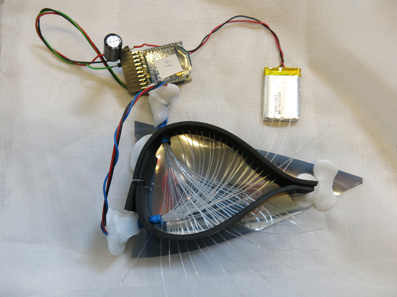
The EyeTo control the LEDs, I have to think about how to control the color and the patterns in time. As a first test I used a similar algorithm as used in N-Polytope for the lasers where I can set the fade in, hold and fade out time, and whether or not the light should be pulsing (and if so, at what rate and with which pulsewidth). With RGB leds however, this may not make as much sense, as just viewing RGB as three different channels of light does not seem satisfactory. Should I control it with HSV values instead? But will this kind of calculation work well on an 8-bit microcontroller?
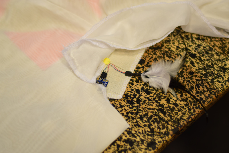
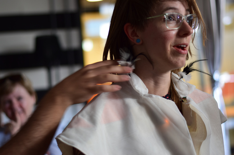
Touch
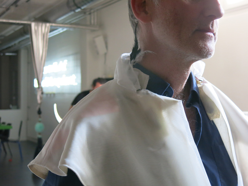
To mediate touch, I already had some concepts: use capacitive sensing on the shoulder and vibration in the neck, as well as small motors that would move feathers to tickle on the cheeks or near the chin. To work on this Tineke had prepared a shoulder piece - a short cape, in which to embed the capacitive sensors and the vibration motors. In the process of further designing the garment, she kept in the back of her mind that we would need to make multiple of these (so keep the process of making as simple as possible), and that we might want to access the electronics to check it, replace it, exchange batteries, and turn it on and off.
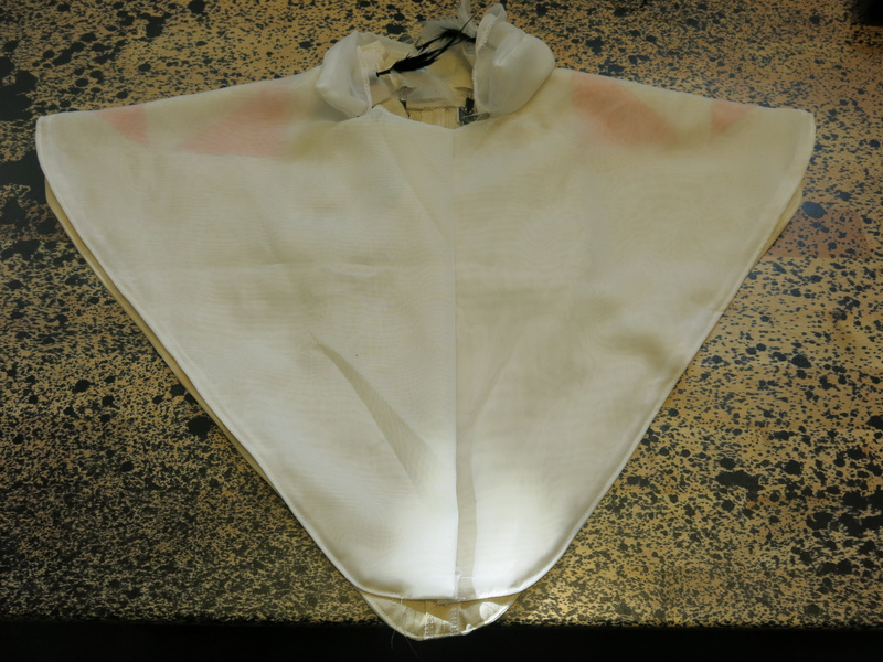

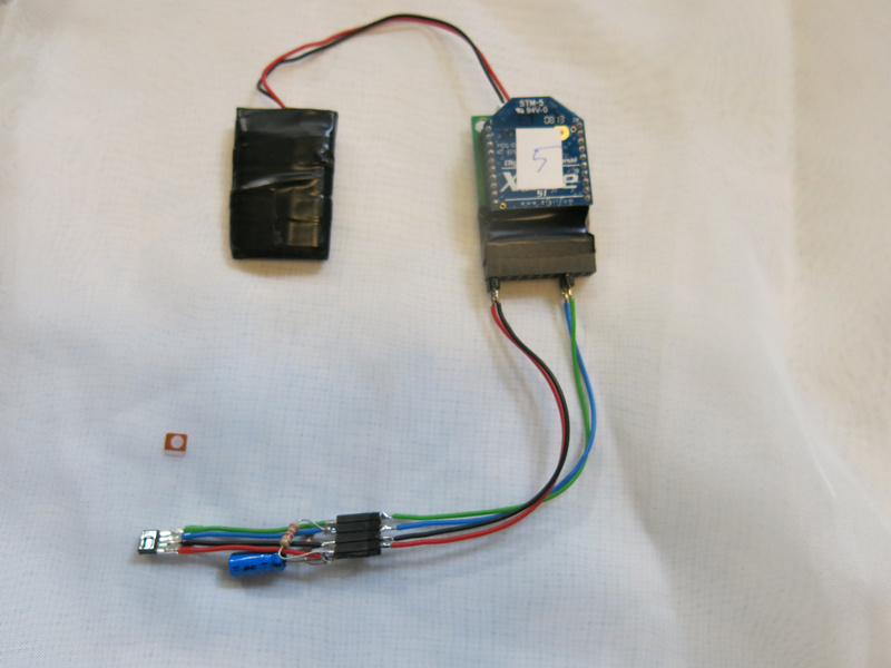
The garment front and backCapacitive sensors
For the capacitive sensors I used the FDC2214 chip from Texas Instruments. This chip can measure capacitance of up to 4 sensors at a high resolution of 28 bits. My idea was to use 3 channels on different locations around the shoulder (front, back, side) and use the 4th channel as a layer underneath to shield a bit the influence of the wearer on the 3 upper sensors. This theory still remains to be tested. Tineke did make a beautiful layout of the sensors and using a white curtain fabric on top, which occludes the sensors slightly, but still keeps them visible enough.
To carry the electronics, she made small pockets on the inside of the back. With a few tiny slits in the fabric behind the sensors, I could attach the copper tape to connect the wiring to the sensing pads, without the wiring becoming visible on the front.
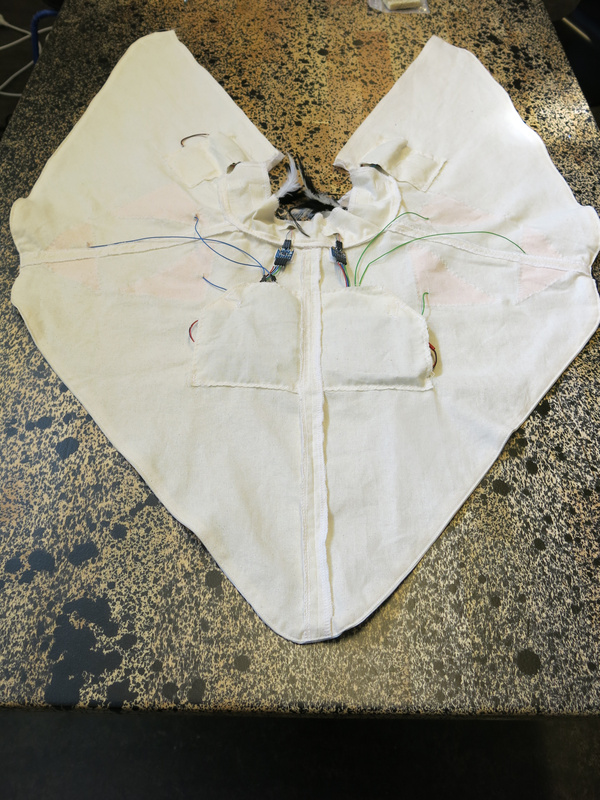
The garment with pockets on the insideTicklers
To give touch feedback to the wearer, we created two ticklers: feathers connected to an ERM (eccentric rotating mass) motor which were mounted in the front of the collar on the right and left side. The construction still needs a bit of improvement, to make:
- the connection of the feathers to the motor a bit more sturdy,
- adjustment possible of the orientation of the feathers, and
- a free way for the feathers to stick out of the collar.
Small 3D printed elements might help to make these improvements.
A first test with wearers made clear that the tickling does work and gives a weird sensation to the wearer.
Vibration
Two small vibration motors in the neck also provide haptic feedback to the wearer. For this the collar should be extended a bit as we realised that our participants may be wearing a blouse with a collar underneath - and then the current location of the motors will be against that collar and the motors will not vibrate in the neck: the wearer won’t feel the vibration.
When we visited Kristina Andersen at the TU Eindhoven, she suggested also another location to put a vibration sensor: a bit lower on the back, between the shoulder blades. We still need to try this location, but it does seem interesting, and since we are mounting electronics around that location anyways, we may as well put a vibration motor there.
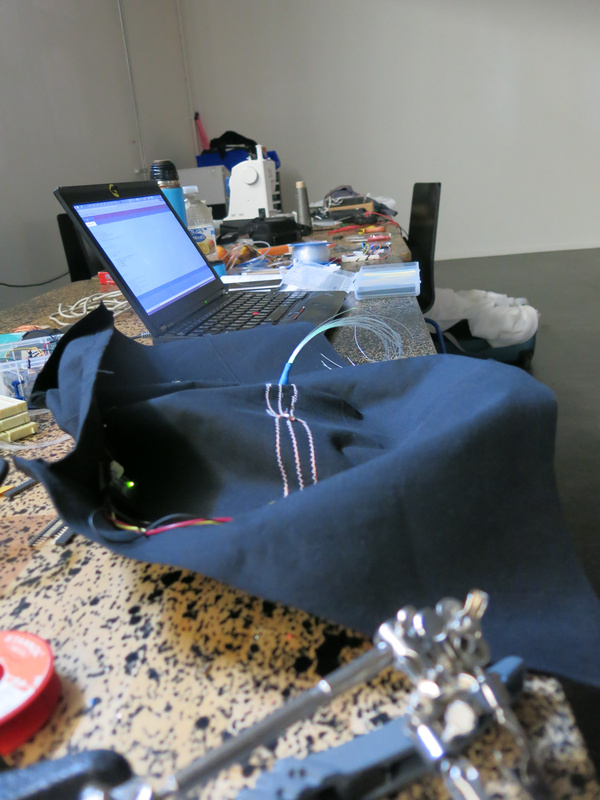
Optimising the electronics
For this small cape, we now use 4 MiniBees to do the sensing and control the haptic feedback. 2 MiniBees with an FDC sensor and a haptic motor driver (the DRV2605L) controlling a vibration motor and 2 MiniBees with a haptic motor driver to control each of the ticklers.
I did attempt to connect both FDC boards to one MiniBee. While in principle this should work (the FDC’s can be given two different I2C addresses), it seemed that the MiniBee was not providing enough current for both boards. I will need to look more closely at this.
The haptic motor driver has no configurable I2C address, so in order to control multiple drivers from one microcontroller, we will need an I2C switch. The TCA9543A (2-channel) or TCA9548A (8-channel) are possible options for this, but I couldn’t get a quickly soldered together version with the 2-channel version working in time, so I put this on my todo list for looking into later. For our design, we would need to drive 5 haptic drivers from one board, so we would need the 8-channel switch.
Design considerations
In our first version we made small pockets for the electronics on the garment. The electronics were thin enough to do this and make the electronics almost invisible while wearing the garment. Nonetheless, we did start to think about how this would look in the final version and came up with the idea to have a small pyramid-shaped pod on the back between the shoulder blades to put the electronics in and also protect them a bit better. We could also make this pyramid light up in a way to reflect what is going on with the sensors and/or the algorithms that act upon the sensor data.
A further consideration is to hook the sensors up to a PocketBeagle (the miniature version of the BeagleBone Black) instead of the MiniBees. That way, I could do more processing of the sensor data locally, which might help in spreading the processor load over all units. The PocketBeagle is also quite affordable, and I could still use either WiFi or XBees to communicate between the different units.
Using this approach, I might end up with two PocketBeagles: one in the garment over the shoulders, and one in the hood, which will contain the mediation of hearing. The latter would then use a MiniBela to capture the sound and play sound back to the wearer. The PocketBeagle in the hood, might then also have connections for the biometric protheses (breath and heart rate at the earlobe) and the vision protheses (the 8x8 thermal vision sensor and controlling the LEDs).
The pyramid shape of the pod and the triangular shapes of the capacitive touch sensors sowed the seed for taking the triangle as a basic shape to use throughout the design. Thus the triangular shape for each eye and first sketches for creating a hood that used the triangle as its basic shape. The future is triangular.
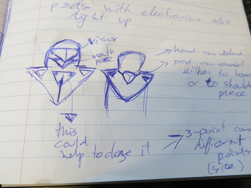
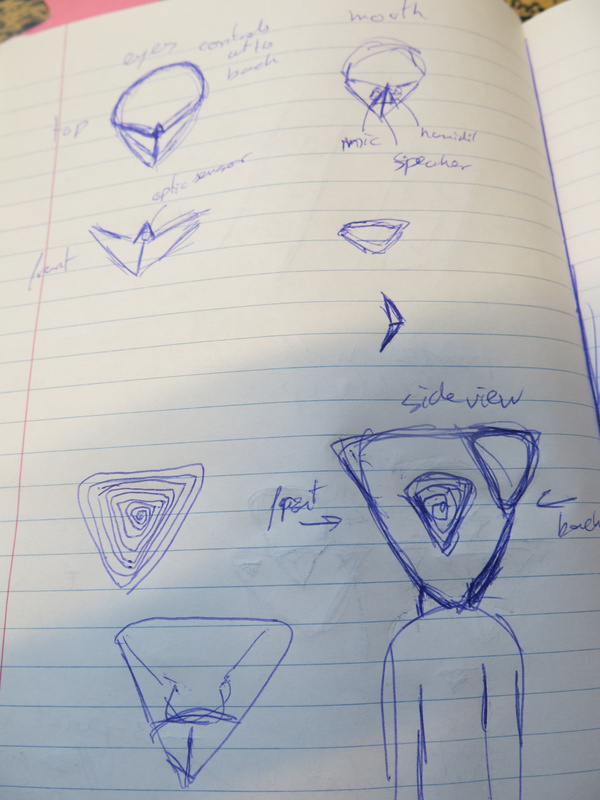
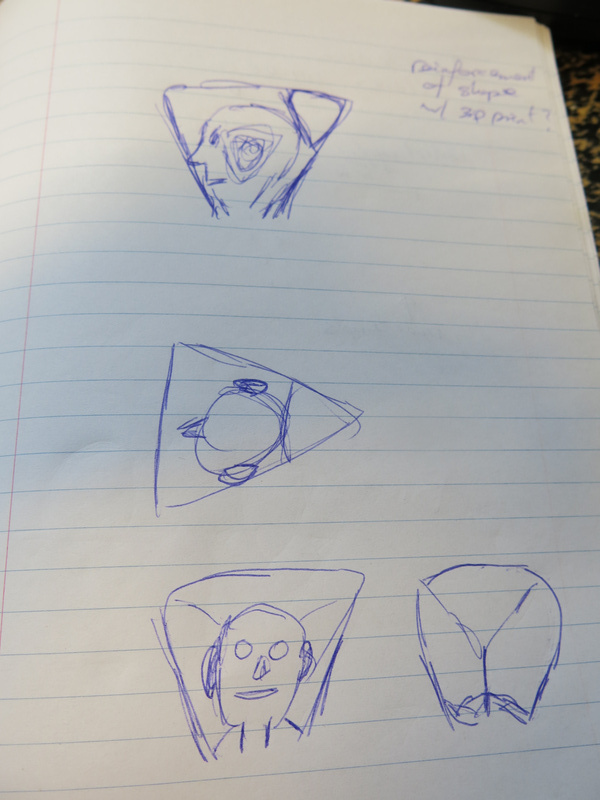
sketches for triangular shapes of the prothesesEmotions
In thinking how the algorithms would mediate the senses, I started thinking about how right now data is tagged on social media. The most popular medium uses 6 possible reactions to posts: LIKE - LOVE - HAHA - WOW - SAD - ANGRY. This suggests that the algorithms behind the medium rate the data (the post) based on these tags: they make associations between what is posted (and probably do some kind of linguistic or image analysis) and the reactions that the post gets. The emotions become the basic reactions that are possible, limiting the nuance of actual emotional experience.
By limiting the possible emotional reactions, I get a compositional tool to use: I can make motives in sound, light and vibraton that reflect these six emotional states and use these states as patterns to recognise when someone is touched (with what emotional intent is someone being touched by someone else), how someone feels (from the biometric data) and what sound or image is associated with this feeling.
Measuring different qualities of touching
During the residency I set up a small experiment to capture data based on these different emotional states. I asked the visitors to the informal show’n’tell on Friday to touch the wearer of the garment in different ways based on the basic emotional tags. As a kind of impromptu exercise it took some time for them to warm up to the idea, but it did evoke different ways of touching - and some between the two groups that were quite similar in gesture. I have yet to see how this translated to the data exactly and whether it would be possible to train a gesture recognition algorithm with these gestures. In the second group especially, it also became apparent that it seemed more easy to think about how the wearer himself would change posture and movement based on the emotion than touching the wearer. Food for thought for designing the next experiments.
Fiction
As a last outcome of this first residency there is a short story written from the perspective of an algorithm or AI (whatever you want to call it). I will type the story up as a separate post.
Conclusion
It was great to work during a focused period on the project. A meeting one week in advance with most of my team (Marion Traenkle, Tim Bosje and Tineke van Hilten) helped to shape some of the ideas before the residency and doing some preparation work at home (basic sensor tests and purchasing all the components I wanted to work with) got me well prepared for the week. Finally just building, making and trying things out in the Baltan laboratory helped shape the concepts and gives a glance of what this project will look like and how it will work.
Looking forward to the next round starting on May 29!
Self-documenting wearing the garment