Building prototypes at Baltan
In the first part of my “Sentient Machines” residency at Baltan Laboratories, I focused on building first versions of the different protheses prototypes to use in the Malbody Centre project. During this residency Tineke van Hilten joined me to help out with creating a wearable.
In this report, I address the various things that I worked on by theme, rather than in chronological order.
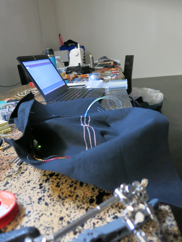
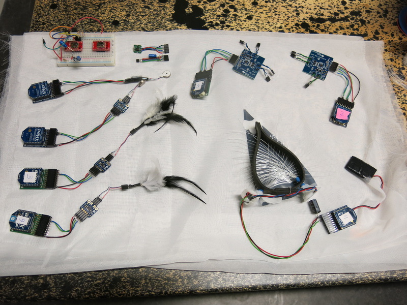
my worktable at Baltan and the different elements I made
Biometric sensing
For biometric sensing, I wanted to try out how to detect breathing and heart rate. For this I got two sensors: a humidity/temperature sensor (a HIH8000 series sensor from Honeywell) and an optical sensor based on a reference design for pulse measurement (the MAX30101 from Maxim).
During the residency I got both of these to work with the Sense/Stage MiniBee to get the data wireless to my computer. I did some very basic tests looking at the data to get a sense whether breath and heartrate could be detected and measured with them.
Breath
With the humidity/temperature sensor I got quite nice results holding the sensor in front of my mouth or in front of my nose. Both temperature and humidity values are fluctuating nicely along with my breath. Humidity occasionally has a shift in overall level when the breathing rhythm is changed, so to make a good measurement of the rhythm, I will need to do some filtering to only look at the fluctuation of the breathing. The data looks promising, so the next step is to figure out how to make something in front of the mouth/nose to mount the sensor. I also would like to combine this sensor with one or two small microphones as an additional way of measuring the air flow and possibly sounds that are uttered by the wearer. And maybe, there should also be a speaker to replace these sounds with something controlled algorithmically.
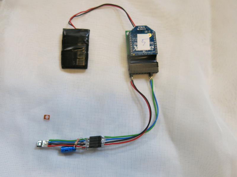
the humidity sensor hooked up to the MiniBee
Heartrate
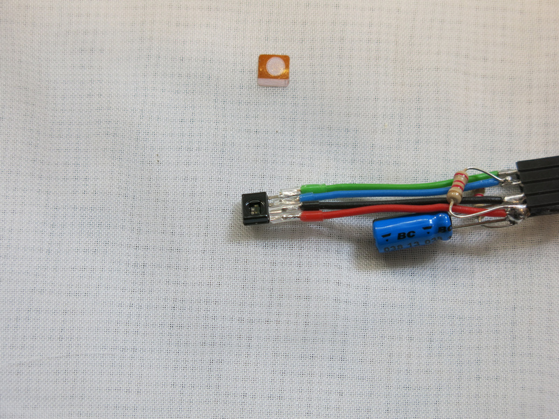
For the heartrate: I got the sensor working and used the algorithm that was provided in example libraries to detect the peaks in the measured signal. While this works fairly well, occasionally a beat is missed or a second peak is detected. That means that either the peak detection algorithm needs to be improved, or I just need to filter a bit for these errors. In terms of placement, I had the impression that placing the sensor on the earlobe is more reliable than placing it on a fingertip. Possibly there are other parts of the body that may work well.
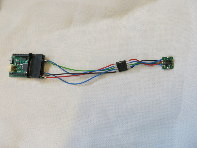
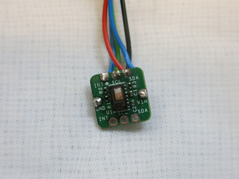
the pulse sensor hooked up to the MiniBee
Vision
For the vision I worked both on the sensor: how the prothesis will see things, as well as how the vision would be altered and mediated.
Thermal vision
For sensing vision, I decided not to use a camera, but instead use a more low resolution sensor. I found a thermal sensor (the AMG88xx) that senses the temperature variations in an 8x8 grid. It does this with quite a good resolution: 0.25 degrees Celsius resolution. From each of the 64 pixels a 16-bit value is obtained from the sensor. To make this work well with sending out the data wireless, I had to package the result in blocks of 16 pixel values as otherwise the package to be sent wireless got too big. But still with this approach I can get an update rate of 20 Hz, which is fast enough for the sensor.
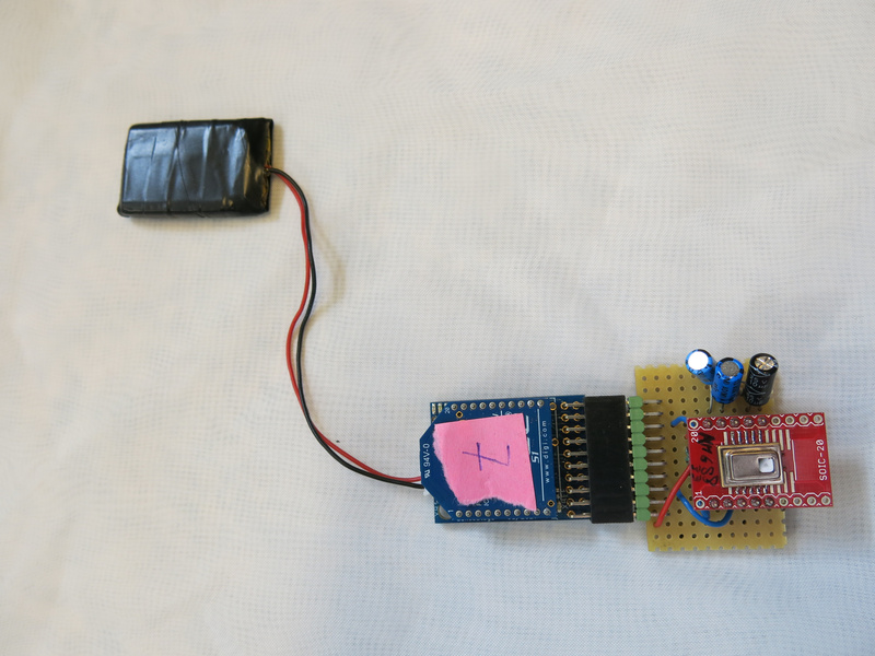
thermal 8x8 grid sensor hooked up to the MiniBee
Blocking vision
To block or let through vision, I had one idea that needed to be tested. I had made a hood, which would cover the head. Inside the hood I attached some LEDs and held a foil in front of my eyes that would either be see through or mirror depending on which side there is more light coming in. This didn’t work as well as I hoped, using multiple layers increased the effect a bit, but that did make it rather dark. So experiment failed.
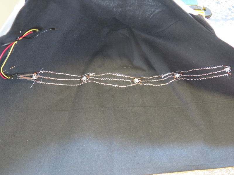
LEDs sewn into the hood
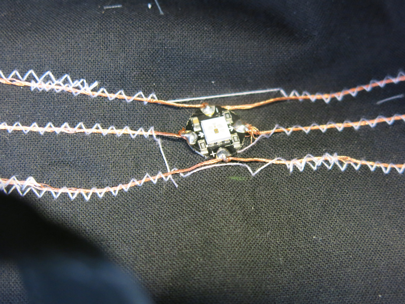
The next test was to see what would happen if I used fiberglass wires for conducting light. This idea came from looking at fabrics that can light up, which also use fiberglass wires. As I didn’t manage to obtain a piece of this fabric, but had a roll of fiberglass wire with me, I decided to make something from these.
testing fiberglass wires on the LED
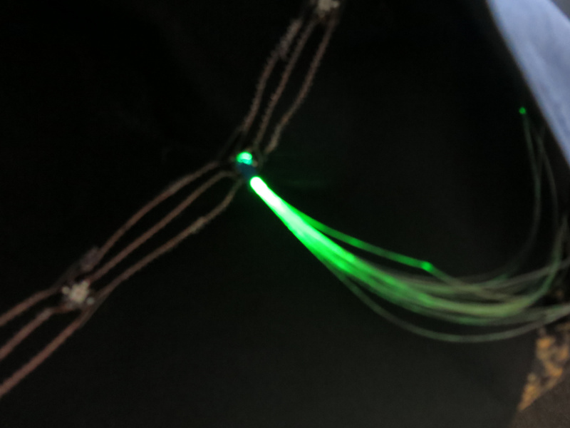
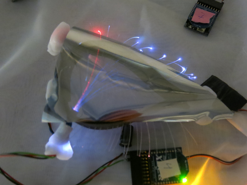
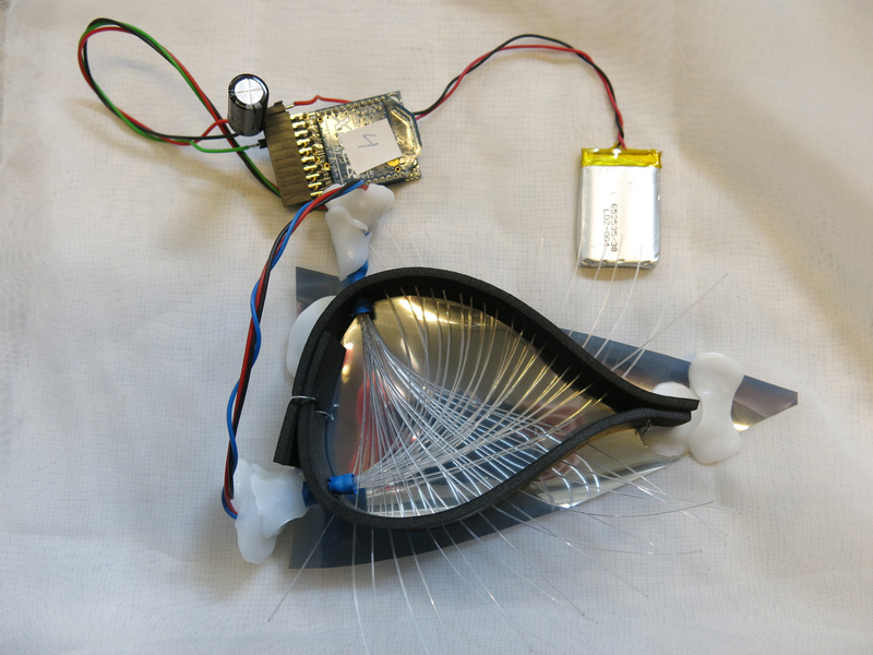
After an initial test to see whether I could get an LED to light up the fiberglass wire, I did some simple tests to see what this would look like when up close to my eyes. The idea seemed promising. Tineke suggested to make a kind of frame for the eye, to hold the fiberglass wire in the right place. So I got some prototyping materials to see how this would work out. From some foam I created a triangular form which would cover the eye. I made some larger holes in it to hold the bundle of fiberglass wire and smaller holes for the singular wires - in such a way that the wires would fan out from the bundle. This in two directions so two bundles of fiberglass wire cross in front of the eye. Making a simple weave it seems that in principle this works quite well, and adding the foil the effect is even enhanced! Now I get the effect that I wanted to have: being able to block the vision, and being able to ‘enhance vision’ by supplying colors to the vision. And the fiberglass wires seem to be enhanced eyelashes too with their endings lighting up.
The prototype looks promising, so the next steps will be to figure out how to make them in a more sturdy manner: fixing the fiberglass wires in front of the LED, roughening up the wires so the light gets out in front of the eyes, and making the frame in such a way that it will stay on the head.
The Eye
To control the LEDs, I have to think about how to control the color and the patterns in time. As a first test I used a similar algorithm as used in N-Polytope for the lasers where I can set the fade in, hold and fade out time, and whether or not the light should be pulsing (and if so, at what rate and with which pulsewidth). With RGB leds however, this may not make as much sense, as just viewing RGB as three different channels of light does not seem satisfactory. Should I control it with HSV values instead? But will this kind of calculation work well on an 8-bit microcontroller?
Touch
To mediate touch, I already had some concepts: use capacitive sensing on the shoulder and vibration in the neck, as well as small motors that would move feathers to tickle on the cheeks or near the chin. To work on this Tineke had prepared a shoulder piece - a short cape, in which to embed the capacitive sensors and the vibration motors. In the process of further designing the garment, she kept in the back of her mind that we would need to make multiple of these (so keep the process of making as simple as possible), and that we might want to access the electronics to check it, replace it, exchange batteries, and turn it on and off.
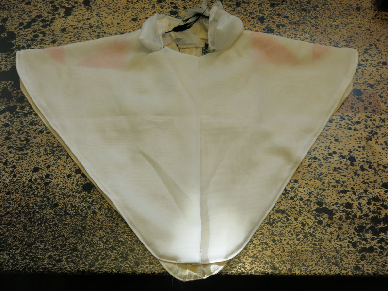

The garment front and back
Capacitive sensors
For the capacitive sensors I used the FDC2214 chip from Texas Instruments. This chip can measure capacitance of up to 4 sensors at a high resolution of 28 bits. My idea was to use 3 channels on different locations around the shoulder (front, back, side) and use the 4th channel as a layer underneath to shield a bit the influence of the wearer on the 3 upper sensors. This theory still remains to be tested. Tineke did make a beautiful layout of the sensors and using a white curtain fabric on top, which occludes the sensors slightly, but still keeps them visible enough.
To carry the electronics, she made small pockets on the inside of the back. With a few tiny slits in the fabric behind the sensors, I could attach the copper tape to connect the wiring to the sensing pads, without the wiring becoming visible on the front.
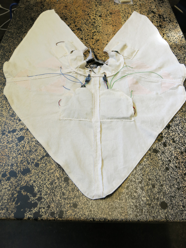
The garment with pockets on the inside
Ticklers
To give touch feedback to the wearer, we created two ticklers: feathers connected to an ERM (eccentric rotating mass) motor which were mounted in the front of the collar on the right and left side. The construction still needs a bit of improvement, to make:
- the connection of the feathers to the motor a bit more sturdy,
- adjustment possible of the orientation of the feathers, and
- a free way for the feathers to stick out of the collar.
Small 3D printed elements might help to make these improvements.
A first test with wearers made clear that the tickling does work and gives a weird sensation to the wearer.
Vibration
Two small vibration motors in the neck also provide haptic feedback to the wearer. For this the collar should be extended a bit as we realised that our participants may be wearing a blouse with a collar underneath - and then the current location of the motors will be against that collar and the motors will not vibrate in the neck: the wearer won’t feel the vibration.
When we visited Kristina Andersen at the TU Eindhoven, she suggested also another location to put a vibration sensor: a bit lower on the back, between the shoulder blades. We still need to try this location, but it does seem interesting, and since we are mounting electronics around that location anyways, we may as well put a vibration motor there.
Optimising the electronics
For this small cape, we now use 4 MiniBees to do the sensing and control the haptic feedback. 2 MiniBees with an FDC sensor and a haptic motor driver (the DRV2605L) controlling a vibration motor and 2 MiniBees with a haptic motor driver to control each of the ticklers.
I did attempt to connect both FDC boards to one MiniBee. While in principle this should work (the FDC’s can be given two different I2C addresses), it seemed that the MiniBee was not providing enough current for both boards. I will need to look more closely at this.
The haptic motor driver has no configurable I2C address, so in order to control multiple drivers from one microcontroller, we will need an I2C switch. The TCA9543A (2-channel) or TCA9548A (8-channel) are possible options for this, but I couldn’t get a quickly soldered together version with the 2-channel version working in time, so I put this on my todo list for looking into later. For our design, we would need to drive 5 haptic drivers from one board, so we would need the 8-channel switch.
Design considerations
In our first version we made small pockets for the electronics on the garment. The electronics were thin enough to do this and make the electronics almost invisible while wearing the garment. Nonetheless, we did start to think about how this would look in the final version and came up with the idea to have a small pyramid-shaped pod on the back between the shoulder blades to put the electronics in and also protect them a bit better. We could also make this pyramid light up in a way to reflect what is going on with the sensors and/or the algorithms that act upon the sensor data.
A further consideration is to hook the sensors up to a PocketBeagle (the miniature version of the BeagleBone Black) instead of the MiniBees. That way, I could do more processing of the sensor data locally, which might help in spreading the processor load over all units. The PocketBeagle is also quite affordable, and I could still use either WiFi or XBees to communicate between the different units.
Using this approach, I might end up with two PocketBeagles: one in the garment over the shoulders, and one in the hood, which will contain the mediation of hearing. The latter would then use a MiniBela to capture the sound and play sound back to the wearer. The PocketBeagle in the hood, might then also have connections for the biometric protheses (breath and heart rate at the earlobe) and the vision protheses (the 8x8 thermal vision sensor and controlling the LEDs).
The pyramid shape of the pod and the triangular shapes of the capacitive touch sensors sowed the seed for taking the triangle as a basic shape to use throughout the design. Thus the triangular shape for each eye and first sketches for creating a hood that used the triangle as its basic shape. The future is triangular.
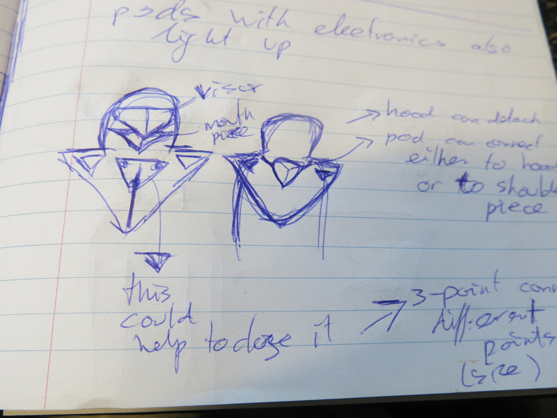
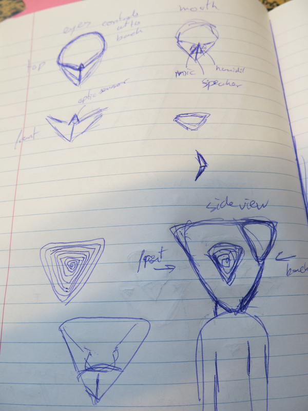
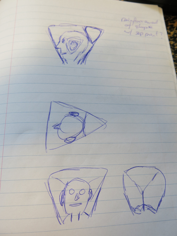
sketches for triangular shapes of the protheses
Emotions
In thinking how the algorithms would mediate the senses, I started thinking about how right now data is tagged on social media. The most popular medium uses 6 possible reactions to posts: LIKE - LOVE - HAHA - WOW - SAD - ANGRY. This suggests that the algorithms behind the medium rate the data (the post) based on these tags: they make associations between what is posted (and probably do some kind of linguistic or image analysis) and the reactions that the post gets. The emotions become the basic reactions that are possible, limiting the nuance of actual emotional experience.
By limiting the possible emotional reactions, I get a compositional tool to use: I can make motives in sound, light and vibraton that reflect these six emotional states and use these states as patterns to recognise when someone is touched (with what emotional intent is someone being touched by someone else), how someone feels (from the biometric data) and what sound or image is associated with this feeling.
Measuring different qualities of touching
During the residency I set up a small experiment to capture data based on these different emotional states. I asked the visitors to the informal show’n’tell on Friday to touch the wearer of the garment in different ways based on the basic emotional tags. As a kind of impromptu exercise it took some time for them to warm up to the idea, but it did evoke different ways of touching - and some between the two groups that were quite similar in gesture. I have yet to see how this translated to the data exactly and whether it would be possible to train a gesture recognition algorithm with these gestures. In the second group especially, it also became apparent that it seemed more easy to think about how the wearer himself would change posture and movement based on the emotion than touching the wearer. Food for thought for designing the next experiments.
Fiction
As a last outcome of this first residency there is a short story written from the perspective of an algorithm or AI (whatever you want to call it). I will type the story up as a separate post.
Conclusion
It was great to work during a focused period on the project. A meeting one week in advance with most of my team (Marion Traenkle, Tim Bosje and Tineke van Hilten) helped to shape some of the ideas before the residency and doing some preparation work at home (basic sensor tests and purchasing all the components I wanted to work with) got me well prepared for the week. Finally just building, making and trying things out in the Baltan laboratory helped shape the concepts and gives a glance of what this project will look like and how it will work.
Looking forward to the next round starting on May 29!
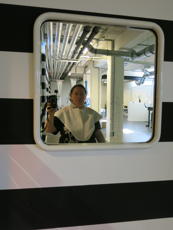
Self-documenting wearing the garment