Behaviours of light and sound
This post was originally written in 2018, but then not published on the website yet. I’m happy to post it now, finally!
In this post, I will describe how the sound and light composition of N-Polytope is structured. For this I will start with the physical components, describe the sound synthesis and light synthesis algorithms, and then go to the bigger picture of the composition with these instruments and how the machine learning algorithms are used.
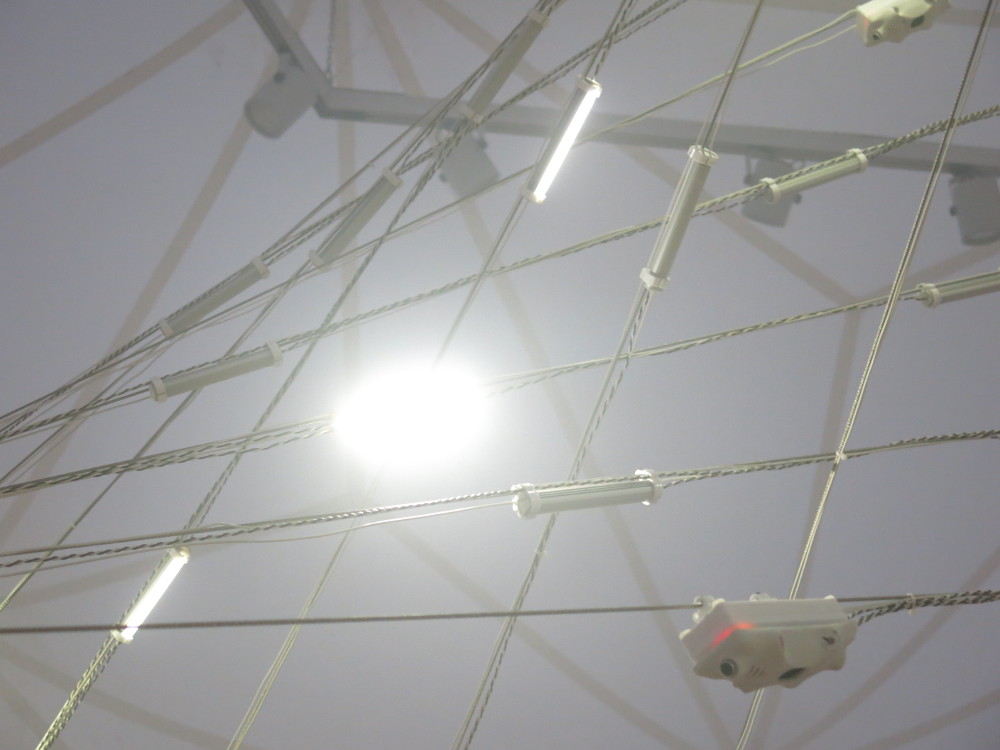
N-Polytope is a re-imagination of Xenakis’s Polytope works. For this work we were inspired to use similar steel cable structures that look like curved planes, folded into each other. For each location where N-Polytope is presented, the steel cable structure is adapted to the space were the work is exhibited and we try to create a connection with the architecture of the space.
On the steel cable structures modules are mounted that generate light and sound and also measure light and sound. The measurements are sent to a central computer which runs various machine learning algorithms over the course of the 14-minute composition. The timeline of the composition is determined by an additional ‘fixed media’ soundtrack composed by Chris Salter and Adam Basanta. This soundtrack is played over 4 broad range speakers situated around the space and 2 subwoofers.
The physical components
The modules on the steel cable structures consist of
- a microcontroller (Atmega328p)
- a second microcontroller (ATTiny841) that is programmed for sound synthesis
- an XBee for wireless communication
- 3 light dependent resistors (LDR)
- 1 electret microphone
- connections to three LEDs which are mounted separately on the steel cable
The Atmega328p is the core of the module and handles wireless communication (via the XBee) with the main computer, measurements of the LDR’s, amplitude tracking of the microphone, communication with the ATTiny841 to control the sound synthesis, and pulse width modulation patterns for the LEDs.
Modular computation
Sound synthesis
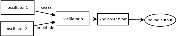
The ATTiny841 is programmed with a fixed sound synthesis patch of three wavetable oscillators, where one oscillator controls the amplitude of the third one, and another the phase of the third one. Then after the third oscillator there is a 2nd order filter. Then the result is sent to a DAC, connected to a small amplifier and the speaker of the module.
Each oscillator has parameters for
- the frequency
- the waveform (sine, sawtooth, triangle, pulse, dc, noise)
- the envelope, with attack and decay
- the duration
- the amplitude
- to play once or repeat the envelope
For the waveform, only the third oscillator can be noise generator (not a wavetable then), and only the first two oscillators can be DC (so not a waveform, but a fixed value).
The synthesizer can be triggered with a wireless message from the computer.
For the frequency and duration parameters you can set a base value and a range within which a random value is chosen upon triggering the synthesis which is added to the base value. Then there are three modes for using the random range: no randomness (so just use the base value for the parameter), setting the randomvalue once when the setting is sent to the synthesizer, and choosing a random value each time the synthesizer is triggered.
Light synthesis
For controlling the lights also a synthesis approach is chosen: the computer just sends parameters for the light pattern and then sends triggers to start the sequence.
For each LED there is an oscillator with
- a range for the intensity between which the LED oscillates
- duty cycle (how long the waveform is)
- frequency
- waveform (triangle, sawtooth, reversed sawtooth, pulse, noise and DC)
- duration
- once or repeat (waveform cycle)
Also here the frequency and duration can be set with a base value and a range for a random value to be added, with the same random modes as for the sound synthesis.
Sensing
The microcontroller is also reading out the microphone data at audio rate and doing a very simple envelope following on the measured value.
And the microcontroller is reading out the three LDR’s at a lower rate (1/6th of the audio rate): the microcontroller switches between reading the microphone signal and one LDR: so a sequence of microphone - LDR 1 - microphone - LDR 2 - microphone - LDR 3, and so on. This sequence ensure that the microphone is read out at a constant sample interval. For the LDR’s the speed is not so important as the light levels change on a much slower time scale.
Communication
Finally, the microcontroller handles the communication with the main computer: it sends out the sensor data at a regular interval, and continuously listens for incoming messages that set the paramaters for the light and sound synthesis or trigger the LEDs or sound.
Also the sound synthesis microcontroller reports its calculated amplitude, which is send along with the sensor data. Reading out this communication also checks that the ATTiny841 is still up and running. If there is no communication for a while, the Atmega328p will reset the ATTiny841.
Concepts
In making these modules, there were a number of considerations.
On the microcontroller I had to negotiate tradeoffs between the processing power of the microcontroller and its memory size, the bandwidth for the wireless communication, and having a flexible system for experimentation and composition. Changing and updating the firmware is a tedious process that involves opening all the housings, taking out the microcontroller board, uploading the firmware, and putting the board back. Not a quick task with around 50 units, mounted on steel cables and for which a ladder or something else may be needed to reach the unit.
We wanted to have a system with many modules - creating actual sound sources that are spread out over the space, rather than using virtual sound sources in multi-speaker sound spatialisation setups. So we chose to do the sound synthesis locally and send over parameters: hence no need for complex cabling and sound cards with many channels. At the same time, of course having a fixed sound synthesis algorithm limits the amount of possible sounds, but we found with the designed algorithm we could reach a large number of different types of sounds: from very resonant ‘rinkling’ sounds to noisy snoring like sounds. And even though each individual module only has a 1W amplifier with a small speaker, all together the system can reach a good level of loudness.
The addition of the randomness to the frequency and duration of the sounds is a way of implementing variation in the sounds: it allows us to use the same preset of parameters for all modules, while still having a variation of sounds. The base value plus a random value within a certain range is also akin to Xenakis’ concept of tendency masks - ranges within which parameters of sound vary over the course of time.
Also using a synthesis approach for the light is remeniscent of Xenakis’ concept of viewing light as something that happens over time: the light synthesis parameters describe how the light behaves within a short time window from its triggering.
The modules implement the possible micro-behaviours for the light and sound. The presets for these are then sent from the central computer. This leaves the freedom to try out new presets when the system is set up in a space, without having to reprogram the modules and at the same time it limits the amount of communication needed to the module (since wireless bandwidth is limited and wired communication would require a more complex setup and a lot more cables).
The compositional structure
As mentioned above the compositional structure then consists of a fixed media soundtrack and a score linked to it, that starts and stops:
- various machine learning algorithms,
- presets and parameter changes for light and sound synthesis algorithms
- additional tasks that sequence the triggering for light and sound
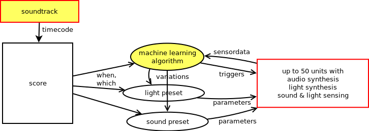
While composing the work, we (Sofian Audry, Chris Salter and myself) discussed the type of algorithms we would use: Sofian would program the algorithms using his machine learning library Qualia and I would choose what type of presets for the microbehaviour of the light and sound would fit to the algorithm and with the soundtrack. Then we would look at the behaviour of the algorithm and tune the parameters for the machine learning algorithm and the presets. The score also determines which modules are active at a given time: so we make interventions on where the machine learning algorithms are active and where not to create a spatial dramaturgy for the work.
The machine learning algorithms
The machine learning algorithms take different types of inputs: we have sensor data from the structure available: light and sound levels, and for some of the algorithms we use different metrics as well.
Some of the algorithms (booster and chaser) are based on reinforcement learning: the algorithm makes an observation (e.g. of the light and sound levels), determines an action to take, and then gets a reward which is calculated from a subsequent observation. The reward is simply a function of the values given in the observation: a mathematical formula. The algorithm then attempts to get the largest reward possible over time. Then it also has a parameter for how ‘curious’ or ‘exploratory’ it is to try out something new: take a complete different action in the hopes that the chosen action yields an even higher reward than it got with previous actions.
For all of the algorithms we are sending a trigger signal to calculate the next step for the calculation. This means that we can vary the speed of the algorithms.
Firefly
In the firefly algorithm each LED has three states: it can be flashing for a certain amount of time and after this time it will be ‘blind’ for a while: it will ignore its environment. If it is not flashing or blind, the LED will measure the amount of incoming light and compare that with the average amount of light over the past time (calculated from a moving average). When above the threshold, the a power variable will be increased and the firefly will be blind for a while.
Then the power variable is compared to a second threshold, and if it exceeds that threshold it will start flashing. If it has flashed for the set flash time, it will reset the blind time and the power variable and go back to the idle state.
Drunk
The drunk algorithm is a kind of random walk: the value for the LED intensity is a weighted sum of a random walk of a parameter for the overall grid, for each line, for each node and the individual LED.
For each parameter at each update a small random amount is added or substracted. Then the total value is calculated by adding the values up with a certain weight for how much influence each of the parameters has. If the weight for the overall grid would be 1 and 0 for the other parameters, all LEDs would do the same. So the weights determine the amount of variation between the individual LEDs: from all the same to all completely different.
This algorithm uses no other inputs than the weights for the four parameters. These weights are changed over the course of the section.
Booster
The booster algorithm has as many agents are there are modules. The agents have a neural network with 5 inputs, 8 hidden layers and 1 output. It then uses an epsilon-decreasing policy for learning, which means that at the start the agent is more exploratory and later on the agent is more greedy.
The inputs to the network are the measured light value, the moving average of the light value, a parameter energy and a timer. The energy is a slowly increasing value with time, and after a certain amount of time after emitting light, the energy increases also based on the light input. The reward is calculated from the emitted led values, with some linearity built in, that boosts the ‘right’ decisions and punishes ‘bad bursts’.
When the agent decides to emit light, the energy and the timer are reset to 0.
Chasers
In the chasers algorithm the spatial layout of the structure is taken into account. Each line is regarded as a one-dimensional space where a chaser can move around. While moving the chaser is rewarded for touching another chaser (be on the same position), moving, or staying in the same position. The position on the line is defined as the position of an LED, so if there are three modules with each three LEDs mounted on a steel cable, that line has 9 possible positions for a chaser to be. The position of the chaser is visualised by triggering the LED and auralised by triggering the sound of the module the LED belongs to. If the reward for the chaser is larger than 0.5 (the range is between 0 and 1), the parameter repeat is set for the light preset.
In the score, more and more chasers are added to each line. Initially the light preset is a short flash. Later on in the chaser section, the light preset is changed to a longer flickering light, creating more overall brightness in the space.
Note that in this algorithm the only input of the algorithm is the position of the other chasers - no sensor data is used.
Genetic algorithm
The genetic algorithm was added in 2017 for the exhibition at the MAC in Montreal. The idea was that instead of setting the parameters for the presets of the light and sound synthesis directly, a genetic algorithm would try to mutate from its current state to the new target state of the parameters. In this way the algorithm attempts to replicate the ‘normal’ score, but takes a bit of time before it has found the right parameter set.
The parameter set is interpreted as a string of bits (1’s and 0’s), a binary chromosome. At each step of calculation of the algorithm, it selects two members of the population, ‘mates’ them to create two new ‘children’ and selects the fittest of the two offspring, i.e. the one closest to the new target preset.
We created two instances of this algorithm: one with a population of the size of the number of nodes to approximate the sound presets, and one with a population the size of the number of LEDs to approximate the light presets.
The ‘genetic’ mode we thus created was then added as an alternative ‘ambient’ mode to play along the ambient soundtrack.